
In A Historic First, 2 Chinese Container Ships Cross Paths Just 75 Nautical Miles From The North Pole

MSC Competes with Maersk For Denmark’s Largest Container Port of Aarhus

Watch: Cruise Ship Collides With Large Piece Of Drifting Ice In Alaska

Canadian Coast Guard Acquires Its First-Ever Autonomous Surface Vessel

Bridge of a Ship – Design And Layout
Ships are massive vessels spanning hundreds of meters in length and weighing thousands of tons. Being able to control and manoeuvre such a large vessel is of paramount importance.
How is it possible for a small crew to operate a ship of such gigantic proportions?
This is where the ship’s bridge comes in.
The bridge is the main control centre of a vessel, from where the captain and officers are able to man the entire operations of the vessel . It is generally located in a position with an unrestricted view and immediate access to the essential areas of a ship.

Historically, the bridge was a structure connected to the paddle house that housed the steering equipment . As it closely resembled an actual bridge, this name was given.
Even after paddle wheels became obsolete and were replaced with the latest technological advents, the term “bridge” still stuck. The master of the bridge is always the captain, who retains control and responsibility of the vessel while he is on board.

During the round-the-clock watch, the highest-ranking officer of the watch is generally placed in charge of the bridge. Only authorized personnel are allowed to enter this area and strict operating procedures must be followed at all times.
The bridge of a vessel houses the main steering equipment, navigation charts , communication systems , engine control as well as miscellaneous features. In addition, some bridges also have adjacent bridge wings, that house equipment for the stern and bow thrusters. These wings extend beyond the main bridge room and provide a clear, unobstructed view of the surrounding areas.
The bridge is always manned by an officer of the watch, who has the responsibility of manoeuvring the vessel and coordinating with the engine room. In general, an officer and a lookout are required to be present on the bridge, to prevent any untoward incidents.
For complicated manoeuvres, the captain of the vessel is often called to the bridge to take over controls. And in areas with a high-risk environment, pilots are often enlisted to guide the ship safely using their knowledge of the region. In addition to being the heart of the ship, the bridge is also used as a command centre and important documents are stored here.
The ship’s papers, permits, important documents, passports, cash for emergencies etc. are kept in safe located on the bridge. For this reason, the entrances into the bridge are often heavily fortified and provided with bulletproof glass to thwart pirate attacks .
In this article, we will take a look at the general layout of the bridge, the various components that are found here and the guidelines to be followed.
Layout and Design of the Bridge
The bridge of a ship is intended to be the heart of the vessel and must provide a clear and unobstructed view of the surrounding area. Even though a host of electronic and navigational equipment is found on the bridge, the primary purpose must be fulfilled.
Thus, the bridge is demarcated broadly into two regions- the area at the fore intended for clear observation, and the remaining area for controls and comms.
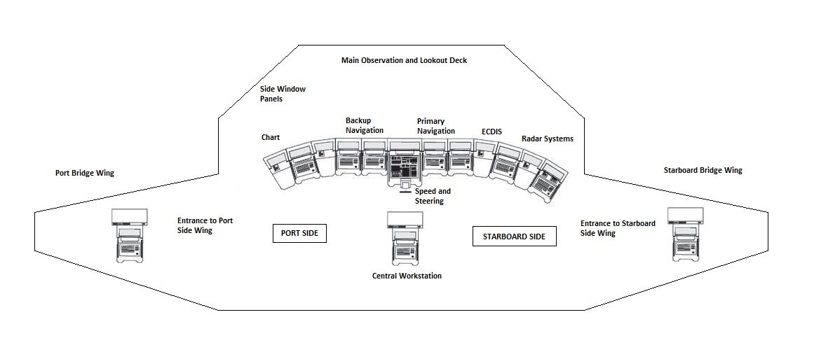
The observation region is enclosed at the fore by large glass panes, built to withstand storms and adverse weather conditions such as hale. Often, plexiglass structures are used and supported on steel or aluminium frames. Shades which can be lowered are also used so that visibility is not reduced when there is a bright light.
Along with the central observation deck, there are also bridge wings. These wings are structures that extend in a transverse manner out of the bridge. Present on the port and starboard side, their primary purpose is to increase the region of visibility, especially during complex manoeuvres such as port docking.

They also house the controls to the individual bow and stern thrusters present on each side. Thrusters are propellers located deep within the hull that provide a higher degree of control to the captain for precise turns and adjustments.
The bridge wings can be either open or closed depending on the type of ship. In most cases, the wings are kept open to allow for maximum visibility. In addition, there is communication equipment found on the wings so that information can be relayed back to the main bridge section. Entry to the bridge wings is restricted to only trained seamen and officers of the watch.
The remaining area of the bridge houses the main navigational, steering and communication equipment. Along with this, there are numerous controls that operate various parts of the ship remotely.
Several internal telephone lines connect the bridge directly to the chief engineer, captain, first officer and the engine room. This enables immediate action based on input from the watch officer.
The control area is built into different console units that are arranged in a semi-circular fashion on all sides of the bridges. This includes radar systems and steering controls that are manned by ship officers.
All equipment used onboard must be IMO certified and must have passed a series of tests intended to check their robust nature and ability to function for protracted periods of time. For safety purposes, fire extinguishers, flares and distress beacons are stored on the bridge.
For anti-piracy reasons, the entire structure is fortified and must pass stringent security checks, especially when sailing through regions such as the Horn of Africa or the Western Indian Ocean region. Although these are hotbeds of criminal activity, most commercial carriers are not allowed to carry firearms or weapons on board.
However, for extreme contingencies, the bridge controls a series of water pumps located all around the ship that thwarts any other vessel from getting too close. Also, special marshals are often hired to provide contracted security and usually keep their firearms on the bridge.
Steering and Engine Equipment on the Bridge
To steer the ship, controls to the rudder , engines and thrusters are present on one of the numerous consoles found in the bridge. Although primary control of the engines rests with the chief engineer or the officer in the engine room, it is an officer from the bridge who often issues commands to the engine room.

To increase speed, there is an engine telegraph that allows for a variety of speeds and even allows the propellers to be put in reverse. There are often different controls for the multiple engines on board. In addition to the engines and propellers, there are bow and stern thrusters that allow for a higher range of precise movements.

The thrusters are often controlled from the bridge wings so that better visibility is available. Thrusters provide steering as their primary function, as compared to power, unlike the engines.
Steering is primarily controlled through the rudder and thrusters, and the controls for both of them rest with the bridge. The rudder must be able to turn to 45⁰ to both the port and starboard side without colliding against the engines. In the case of azipods or integrated propulsion systems, a larger command centre is often used due to the highly sensitive nature of the equipment.
Azipods are an interesting technological invention that allows conventional engines to be integrated with rudders. Thus, a set of azipods are capable of achieving nearly 100% efficiency by turning in almost any direction. This removes the need for different controls for the propulsion and steering systems. In general, controls for the port side are colour-coded red, while the starboard side is often coded green. This allows for easier control by the officers and seamen.
Navigation and Communication on the Bridge
Navigation is a key component of a vessel that is the only means of getting the vessel safely from port to port. Basic navigation equipment includes a Global Positioning System (GPS), Navtex receiver, Electronic Chart Display and Information System (ECDIS), radar systems and communication channels.

Navigation is often controlled using charts that are used to plot routes. To ensure that the vessel stays on course, a combination of GPS and a compass system are used. The charts and equipment are stored in separate locations to ensure the compartmentalization of the bridge. In addition to this, binoculars are used in the daytime for sighting. However, when the weather is not clear, visibility is low or during the night, the radar must be used to accurately place and navigate the ship.
When using radar, a range scale must be used based on the speed and traffic around the vessel. Ships weighing more than 10,000 gross tons must use two radars for potting their course and navigation.
Automatic Radar Plotting Aid (ARPA), Electronic plotting Aids (EPA) and Automatic Tracking Aids (ATA) are also a must on such vessels. Alarms to warn about impending collisions, equipment failure etc. are also used to indicate errors. In certain zones onboard the ship, indicator lights are used to signal warnings.
Bridge Guidelines and Requirements
When at sea, vessels must maintain the strictest of protocols to ensure SOLAS and IMO regulations . As the bridge controls the entire ship, it is essential that the bridge and all equipment satisfy guidelines. For navigation purposes, the bridge must be located with a clear view both ahead and abeam. There must also be a minimum vision of 255⁰ present for the officer on watch (OOW), with at least 112.5⁰ visibility on both the port and starboard sides.

For the bridge wings, the side of the vessel must be clearly visible with 180⁰ on the side and 45⁰ to the opposite side. For the officer in charge of steering, 60⁰ on both sides is the minimum clear visibility.
Ships weighing more than 10,000 gross tonnages must include a single X band – 9 GHz frequency radar. This is according to IMO guidelines for navigation and steering. In case of any contingencies, alarms are positioned at all zones onboard the vessel. These alarms indicate failure of various equipment on the bridge.
In addition, failure or damage from other parts of the ship is also relayed back to the bridge for immediate action. If there is no response from the officer on watch, a backup alarm is signalled after a duration of 30 seconds. This backup alarm is sounded in the offices, mess and cabins indicating a need for assistance.
The Bridge of a Warship
Warships often have a number of bridges that serve multiple purposes. For instance, a navigation bridge houses all navigation-related equipment and charts. It is here that the actual route plotting is completed and relayed to the captain’s bridge. This bridge houses radars that are used for both navigation and military capabilities.
A captain’s bridge is also present, where the captain controls the vessel and the essential components of the warship. When the warship is a central vessel of a fleet or the flagship vessel, it usually has a separate Admirals bridge that is used for strategic and command purposes. Here, the control of the vessel is separated from the control of the vessel. The military staff controlling the fleet are usually housed within this bridge.
Bridge Simulator Systems
The bridge houses extremely sensitive equipment. Being able to successfully sail through a waterbody requires extensive training on the bridge. On average, officers spend years honing their skills before ever being given control of the bridge. In addition, since control over nearly every part of the ship is exercised from the bridge, only trained and authorized personnel are allowed to enter. For training purposes, it is not feasible to give a fresh recruit command over an entire vessel. This is where bridge simulators come into play. They are similar to airplane cockpit simulators but are considerably larger.

Most training institutes have their own simulators that enable recruits to practice on them before actually being deployed onboard a vessel. Several shipping companies also offer specialized simulation software that can be programmed to display a wide range of scenarios.
For instance, MARIN in the Netherlands manufactures and sells various simulation units that project realistic situations to the training officers. A select number of individuals are allowed into the simulator and are allowed to practice. Various types of simulators exist that can be used to test response under different visibility ranges. For instance, although the ideal range of sight must be 270⁰, certain simulators can be programmed to test the ability of the officers to handle a lower visibility range.

Bridge Equipment For Navigation And Control Of Commercial Ships
- Bridge Equipment For Navigation And Control
- For all maritime professionals
- 4 FREE Bonuses
- Read Instantly
- Guaranteed For 30 Days
Disclaimer : The information contained in this website is for general information purposes only. While we endeavour to keep the information up to date and correct, we make no representations or warranties of any kind, express or implied, about the completeness, accuracy, reliability, suitability or availability with respect to the website or the information, products, services, or related graphics contained on the website for any purpose. Any reliance you place on such information is therefore strictly at your own risk.
In no event will we be liable for any loss or damage including without limitation, indirect or consequential loss or damage, or any loss or damage whatsoever arising from loss of data or profits arising out of, or in connection with, the use of this website.

About Author
Ajay Menon is a graduate of the Indian Institute of Technology, Kharagpur, with an integrated major in Ocean Engineering and Naval Architecture. Besides writing, he balances chess and works out tunes on his keyboard during his free time.
Read More Articles By This Author >

Do you have info to share with us ? Suggest a correction
Daily Maritime News, Straight To Your Inbox
Sign Up To Get Daily Newsletters
Join over 60k+ people who read our daily newsletters
By subscribing, you agree to our Privacy Policy and may receive occasional deal communications; you can unsubscribe anytime.

BE THE FIRST TO COMMENT
Leave a reply.
Your email address will not be published. Required fields are marked *
Subscribe to Marine Insight Daily Newsletter
" * " indicates required fields
Marine Engineering
Marine Engine Air Compressor Marine Boiler Oily Water Separator Marine Electrical Ship Generator Ship Stabilizer
Nautical Science
Mooring Bridge Watchkeeping Ship Manoeuvring Nautical Charts Anchoring Nautical Equipment Shipboard Guidelines
Explore
Free Maritime eBooks Premium Maritime eBooks Marine Safety Financial Planning Marine Careers Maritime Law Ship Dry Dock
Shipping News Maritime Reports Videos Maritime Piracy Offshore Safety Of Life At Sea (SOLAS) MARPOL
WAIT! Did You Download 13 FREE Maritime eBooks?
Sign-up and download instantly!
We respect your privacy and take protecting it very seriously. No spam!
- Yacht Sales
- Destinations
- Monaco Grand Prix
- About Ahoy Club
- Meet The Team
The Anatomy of a Yacht | Superyacht Terminology
Whether cruising with family and friends or enjoying an adventurous sailing trip, yachts can offer everything you need for the perfect holiday. Before stepping board, it can be useful to familarise yourself with the parts of a yacht to understand the language and terminology used by the crew onboard, and to appreciate how these impressive vessels work. From the keel to the sails, it's important to understand the anatomy of any vessel before setting out on a chartering journey.
The Parts of a Yacht - An Overview
Understanding the parts of a yacht not only improves your sailing experience but will also increase your appreciation of these powerful vessels. A standard yacht has several key parts, including a stern, hull, and bow. The stern, or aft, refers to the back the yacht, sometimes accompanied by a swim platform. On the other end of the vessel, the bow refers to the front of the yacht. The part of the yacht that floats in the water is referred to as the hull. Most traditional yachts have one hull, however catamarans are typically ‘multi-hull' having two points of contact with the sea.

Mischief superyacht was designed with an iconic French navy hull and white boot stipe.
Hulls – Materials and Design
As hulls are one of the largest components of a yacht, it is important that the design is intentional to withstand the elements on the ocean. The material that is it constructed of varies depending on the vessels size and intended use; it is common to see hulls made from wood, steel, or composite materials. Hulls play a crucial role is ensuring stability on board and a smooth journey as conditions on the ocean can vary.
Bridge & Bridge Deck
Port side & starboard side.
These terms refer to the left and right sides of a yacht; Port side refers to the left side, while starboard side is the right. A helpful tip is to remember the saying “there is a little bit of port left in the bottle.” This terminology is often used by crew in order to effectively communicate with their team in order to avoid accidents and safely navigate the seas, so you will likely hear these terms onboard your stay.

Lady Pamela’s large swim platform ideal for fishing or setting off paddleboarding.
Yacht Main Salon and Swim Platform
There is plenty of fun to be had in these two areas of a yacht. The main salon refers to the main living room onboard and is a space where yacht designers can showcase their personality in the design. Often featuring plush seating, stylish decor and high-end entertaining systems, guests can comfortably enjoy downtime relaxing and socialising in this area. The swim platform is exactly what it sounds like; it offers a convenient way to jump in to cool off and enjoy the water. When you feel it’s time to take a dip, the swim platform is the perfect spot to soak up the sun, enjoy the available watertoys , dip your feet in the ocean, or take a refreshing dive or snorkel in the sea.
All of these elements are thoughtfully designed by experts across the world to construct the magnificent yachts that we know and love. We encourage you to experience our favourite vessels for yourself through luxury yacht hire to appreciate the impressive design and craftsmanship. Our team is here to help you plan your dream holiday on board today.
You May Also Like

mischief superyacht

sirenuse superyacht

Luxury Yachts | Choosing the Right Yacht for You
Make an enquiry, make an enquiry.

- Career Advice
- Salary Guide
- Digital Dockwalk
AI and Smart Tech: The Future of the Superyacht Bridge

Nearly every year, the creative brain trust at Feadship’s De Voogt Naval Architects, Design Studio De Voogt, shares design projections leaping toward the future. These advanced concepts that go far beyond profile renderings are designed to inspire. Rather than imaginative artwork ungrounded by practicality, they include engineered solutions down to propulsion packages, safety regulations, general arrangements, articulating platforms, and glass and finishes concepts. The full plate of innovations — debuted at Monaco Yacht Shows with names such as Breathe , X-stream , Relativity , Royale , Qi , and Choice — aren’t necessarily expected to emerge on a single finished yacht, but emerge they do in elements, pushing a corner of the envelope here and tugging the edges of innovation there. The propulsion concepts for Breathe famously made their way to Savannah , for example.
The Pure Concept
The 81.75-meter Pure concept introduced at the 2021 Monaco show to oohs and ahhs for its smoothly curved, minimalist exterior and for its main and upper deck living spaces designed to blend the indoor and outdoor environments in a dramatic way. But there is another feature far beyond aesthetics that will cause lasting discussion, and one which is ripe for development: Pure ’s hidden bridge. By eliminating a bridge deck, the yacht gains a much sleeker, lower profile with all the knock-on effects that brings to motion and stability without compromising owner lifestyle. In fact, this concept is all about lifestyle — at least Studio De Voogt’s vision for how owners will want to live in the future.
Visual and social connections via open-plan architecture, tiered-yet-connected aft decks, and a massive three-story atrium stretching define the plan. Yes, we are assured, it could be built to full classification standards. As for the current design darling — sliding glass walls — there are a lot of them, and foldout platforms (yawn) on the lower deck. But let’s return to the hidden (Feadship prefers the term “concealed”) bridge. If the deck above main is the owners’, and the forward main deck is a tender garage, where is the wheelhouse? Actually, in terms of stability, it’s in one of the best places on the ship — low, just slightly forward of amidships and offering incredible adjacencies to crew areas and mechanical spaces.
What’s missing is the 180-degree wall of windows to see through when you drive the boat. Take a moment while your brain wraps around that concept.
The first point is to understand that this is NOT a concept for a remotely controlled yacht. Pure has a full crew just like any other vessel of her tonnage and horsepower. This concept will, however, take a big leap into the use of electronics and computational power for enhanced situational awareness on the bridge. Instead of the baby steps of a heads-up display here or there, or an instrument overlay on a single chart screen there, this is the entire kit synced to work together in real time. If it sounds like a futuristic Star Trek Enterprise bridge, you will be surprised to know this “concept” is already in operation aboard commercial and military ships — submarines have no bridge windows after all, and neither do tanks.
- Is ECDIS Just Another Charting Program?
Imagine the “bridge” has become a command center that’s like a theater in the round with Google glasses. And like Google glasses, it utilizes sensors and cameras and artificial intelligence that analyze all the data in microseconds for situational analysis. In addition to input from onboard sensors, cameras, and thermal imaging, GPS, weather and sea state data, ECDIS, LIDAR, RADAR, and SONAR, an almost unlimited amount of data could be added to the stream. This is currently being done on tugs, ships, and coastal ferries in European waters that are being helmed either full-time or during harbor maneuvers by remote fleet command centers assisting onboard crew.
By eliminating a bridge deck, the yacht gains a much sleeker, lower profile with all the knock-on effects that brings to motion and stability without compromising owner lifestyle.
This is the sort of setup that would support totally unmanned cargo or tanker operations or drones. While the fleet command systems in operation may also make use of Virtual Reality simulation, the Studio De Voogt concept does not rely on virtual reality or shore-based captains, but on onboard crew who manage all the tasks — just without looking out windows from prime real estate.
“The concealed bridge concept could be used on vessels of all sizes, but will have the most benefit, I think, to the under 500 GT yacht because it is difficult to arrange a main deck master that has forward views and deck access. Owners these days want their cabin with views, so you would have to make the master aft on the bridge deck or add another deck above, but within your tonnage,” says Tanno Weeda, who along with Jan Schaffers, masterminded the concept for presentation in Monaco. They have well-developed plans for the concept at 1,800 GT and 3,000 GT.
Part of the value in presenting the concept was to obtain crew feedback. Did they get that?
“Oh yes,” says Weeda. Contradicting my suspicions, he notes, “The captains were not that negative, especially the younger ones.”
Schaffers notes that the sentiment seemed to be, “The yacht is for the owner and I am there for the owner, and if this makes it better for the owner, I can do it.” Weeda adds that they were very attuned to crew feedback. “We need the input from the crew to make sure we make the yacht work for the client,” he says. “The most important thing they asked for was wing stations,” says Weeda, which, along with a flying bridge on the sun deck, they could already point to in the plan. Wing stations, a stern station, and/or a portable helm pack would be used for docking or anchoring maneuvers and then disappear. They highlighted that the concealed bridge preserves owner and guest privacy on fore and aft decks — no need to set the helm aft or extend a brow to shield a Jacuzzi or lounge on the deck below from wheelhouse view. And, unlike the current mindset that the bridge needs an open view forward (for most of maritime history, a vessel was controlled from a position aft) a fully integrated smart bridge can be located virtually anywhere on the vessel.
This could be a game changer not unlike that which took place when engine rooms were first moved aft of amidships, completely revamping lower deck accommodation layout options or when beach clubs moved forward from the stern with folding terraces port and starboard instead. They said there are two active discussions with clients for this concept at present.
- How New Satellite Tech Will Affect Yacht Internet Connectivity
Adapting the Concealed Bridge
As Schaffers and Weeda explained, the Pure concept of the concealed bridge can adapt to each project and would differ if the intention is that the captain and watch officer work alone or in teams. In their initial concept, they made it a hub of crew life and completely rethought crew movement paths around the yacht. They noted immediate benefits to the scheme such as dedicated radio rooms — a feature often eliminated (along with a crew dayhead) to preserve more owner real estate on an upper deck. “Another feature is that you can combine things with this space, such as a place to hold crew meetings or training. It shortens the distance dramatically between command and engineering spaces and off-watch crew in case of an emergency,” Weeda comments.
On the other hand, while in port, the wheelhouse sometimes becomes a crew hangout space or a private place to write an email or work on an online course. They said that would need to be considered in the GA to ensure crew welfare is maintained. And of course, whether it is going to be open to guests or not would affect its size and amenities. Both Weeda and Schaffers feel that it would be of high interest to guests when the yacht is underway, or when discovering what travel or activities were planned for the day as shown on large display screens.
The command center presented with Pure is not unlike the training simulators familiar to captains and aspiring officers with work zones arrayed under monitors displaying input from cameras and electronics. A large, curved monitor could display a full 270-degree view of the environment in real time with augmenting information popping up as appropriate on the “picture window” while engine and systems data stay displayed on individual monitors.
Conforming to Code
But how would this mesh with LY3? For the answer, we turned to Section 18.2 of the Red Ensign code on bridge visibility, which directed us to SOLAS Chapter V, sections 15, 19 22, 24, 25, 27, and 28. It turns out such an idea is not specifically prohibited. A view of the sea and horizon from the con is discussed but it does not say where that con has to be or if it can be the flying bridge or wing stations — which are in fact mandated along with their degrees of visibility fore and aft. It is stated that for vessels not less than 45 meters, the view of the sea surface from the con position cannot be obscured by more than two ship’s lengths or 500 meters, whichever is shorter. Bow cameras and LIDAR certainly can be expected to give a superior view to that.
In one section, a range is given for the height of windows as measured from floor and overhead and their maximum incline, but nowhere does it say you must have windows, or how many. In fact, in commercial practice now in harbors in northern Europe — Norway being the leader — the con is often an array of screens at fleet control where a shoreside captain with every imaginable sensor and perspective view at his or her disposal actually takes the helm of in- or outbound ships. The benefit to this augmented intelligence (AI) system at night or in poor conditions over a ship-bound pilot is obvious.
Rolls-Royce and Kongsberg — leaders in autonomous ship development — debuted these systems six years ago. Iiro Lindborg, General Manager, Remote & Autonomous Operations for Rolls-Royce, says, “AI is undoubtedly one of the most significant advances made to-date in terms of ship navigation safety. It provides bridge personnel with a much greater understanding of the ship’s surroundings.” The company expects passenger ships to be one of the biggest markets.
In the Far East, Japanese ship specialist Mitsui is installing an AI system aboard a 165-meter passenger ferry, Sunflower , which operates between Kobe and Oita, Japan.
On a slightly different note, in the U.S., Sea Machines introduced SM200, moving control of towing and harbor vessels outside their wheelhouses. Captains using the SM200 have propulsion and steering control in their hands, wherever they might be on board. It was approved by the ABS and the U.S. Coast Guard for use in articulated tug barges in early 2020. While this gear is designed to be used by a captain on deck, this is a precedent-setting step in the break from a fixed helm position.
With the power of systems like these, as well as increased acceptance for autonomous ship operations, more change is inevitable for yacht control stations, and if yachting follows military and commercial shipping, the buzz will be all about augmented intelligence or enhanced situational awareness for captain and crew. Feadship is betting that one radical idea can lead to safer and more efficient operations while at the same time enhancing owner and guest lifestyle.
This feature originally ran in the July 2022 issue of Dockwalk.
More from Dockwalk
Most popular on dockwalk.
What Is The Bridge On A Ship?
Ever wondered where the control station of massive ships is located where it is operated from? Ships are enormous vessels that can stretch hundreds of meters in length and carry thousands of tons. It is critical to be able to operate and maneuver such a massive vessel safely.
The bridge is a vessel’s principal control center, from which the captain and officers can manage the whole vessel’s operations. It is usually placed in a position with an unobstructed view and immediate access to the ship’s vital controls.
In this post, Let us look into how the bridge has evolved, what are the primary functions it plays, the basic design of the bridge, its many parts, and the rules that must be adhered to.
The History Of The Bridge On Ships
Historically, the bridge was linked to the paddle or wheelhouse, which contained the steering machinery. This name was given because it resembled a real bridge.
Even when technical advances rendered paddle wheels obsolete, the term “bridge” persisted. The captain is always the master of the bridge, and he retains control and accountability of the vessel when on board.
The Bridge: A Central Control Hub
The bridge is a ship’s primary control center, serving as a hub for crucial operational activities, communication, and decision-making. The work environment and activities are highly complex and safety-critical because the bridge is situated on a structure that frequently functions in severe and unpredictable conditions.
A vessel’s bridge houses the major steering equipment, navigation charts, communication systems, engine control, and other elements. Furthermore, some bridges feature neighboring bridge wings that house the stern and bow thruster machinery. These wings extend beyond the main bridge chamber and offer an unimpeded view of the surroundings.

An officer of the watch is always present on the bridge, controlling the ship’s movements and communicating with the engine room . To avoid any untoward incidents, an officer and a lookout must typically be present on the bridge.
On the bridge, a safe is used to store the ship’s papers, permits, critical documents, passports, cash for emergencies, etc. To prevent pirate attacks, the bridge’s entry portals are frequently strengthened and commonly equipped with bulletproof glass.
Bridge Design And Layout
The design of the bridge will vary depending on the ship. But it should be noted that the bridge arrangement generally adheres to the same fundamental design and layout regardless of the type of vessel.
A ship’s bridge is supposed to be its central control hub, offering an unimpeded view of the surroundings and quick access to all controls. The main goal of navigation must be achieved in terms of visibility despite the bridge’s abundance of electrical and navigational technology.
The bridge is roughly divided into two sections: the fore area, which is intended for clear observation, and the remaining area, which is for controls and communications.

The observation area is protected from storms and other bad weather by a wide glass wall that surrounds it at the front. Often, steel or aluminum frameworks are utilized to support plexiglass structures. Additionally, lowering shades are employed to ensure that visibility is not compromised by bright lighting.
The primary navigational, steering and communication apparatus is located in the remaining space of the bridge. Other controls can be used to remotely control different ship systems, for example, cargo or ballast systems .
The control area is incorporated into various console units that are arranged on each side of the bridges in a semi-circular pattern. This includes steering wheels and radar systems operated by ship officers .
A bridge will typically have a captain, a chief mate, a second mate, a third mate, competent seamen, and regular seamen depending on the type of ship.

What Are Bridge Wings?
Bridge wings are present in addition to the central observation deck. They are on the port and starboard sides, and their main function is to widen the visibility area, particularly during difficult maneuvers like port docking.
Additionally, they contain the controls for the separate bow and stern thrusters that are located on either side. Deep inside the hull, thrusters are propellers that provide the captain more control over the ship so they can make precise maneuvers and changes.

Depending on the type of ship, the bridge wings can be either open or closed. The wings are typically left open to allow for optimum visibility. To convey information back to the main bridge section, communication equipment can also be located on the wings. Only skilled seamen and watch officers are permitted access to the bridge wings.
Steering And Engine Layouts On The Bridge
Controls for the ship’s rudder , engines, and thrusters are located on one of the several consoles in the bridge. The chief engineer or the officer in the engine room has the main responsibility for engine control, but an officer from the bridge frequently gives orders to the engine room.
The propellers may also be turned in reverse thanks to an engine control unit, which also allows for a different range of speeds. The numerous engines on board frequently have their controls. There are bow and stern thrusters that enable a wider range of transverse precise motions in addition to the engines and propellers.

The bridge is where the controls for the rudder and thrusters are located, which are used largely to maneuver the ship. The rudder is designed to be able to turn 450 degrees to both the port and starboard sides. In the case of more advanced systems like azimuth or integrated propulsion systems, a larger command center is frequently used.
An intriguing technological advancement is the use of azimuthal propulsion systems, which let regular engines and rudders work together. They turn in practically any direction and achieve efficiency close to 100%. This eliminates the requirement for separate controls for the steering and propulsion systems. Controls on the port side are typically color-coded red, while those on the starboard side are frequently coded green. The officers and seamen can maintain control more easily as a result.
Navigation And Communication Equipment
A vessel’s navigation system is a vital part because it is the only way to transport it securely from one port to another. A Global Positioning System (GPS), Navtex receiver, Electronic Chart Display and Information System (ECDIS), radar systems, and communication channels are all considered to be basic navigational tools.
Charts that are used to plot routes are frequently utilized to regulate navigation. A GPS and compass system are used to make sure the boat stays on course. To maintain the bridge’s compartmentalization, the charts and equipment are kept in different places. Additionally, binoculars are utilized for sighting during the day.

However, the radar must be used to precisely position and navigate the ship when the weather is not clear, visibility is poor, or it is dark out. When utilizing radar, a range scale that takes the speed and nearby traffic into account must be employed. Ships weighing more than 10,000 gross tons are required to navigate and plot their path using two radars.
On such warships, automatic tracking aids (ATA), electronic plotting aids (EPA), and automatic radar plotting aids (ARPA) are also essential. Errors are also signaled by the same alarms that are used to warn about approaching collisions, equipment failure, etc. Onboard the ship, warnings are signaled through indicator lights in specific areas.
Drawbacks Of A Poorly Designed Bridge
Tasks performed by the ship’s crew and navigation team involve interacting with both people and technology (the various equipment and systems of the bridge and ship). Onboard the ship and with outside parties, this calls for engagement and communication between people and technology (e.g. port control, Vessel Traffic Service, surrounding ships, onshore facilities, etc.).
Technology-wise, the bridge is a complicated system. A merchant ship’s typical bridge equipment may include things like:
- an autopilot,
- conning displays,
- Automatic Radar Plotting Aid (ARPA),
- Electronic Chat Display and Information System (ECDIS),
- Dynamic Positioning (DP),
- Global Positioning System (GPS),
- Gyrocompass,
- various communication devices required by GMDSS
- and a combination of other systems and sensors.
A single bridge could be made up of dozens of pieces of equipment from many brands and suppliers. The design and layout ideas used by these companies for hardware and software components are often unique.
The crew may experience issues once the equipment has been built and integrated into a single working environment (such as the bridge), which calls for the employment of the equipment in tandem. Consequences for the crew have been demonstrated as a result of inconsistent design across these many pieces of equipment and interfaces, and it has even been suggested that such inconsistent design may have contributed to maritime accidents.
Bridge Rules And Guidelines
Vessels must adhere to the toughest protocols while at sea to guarantee that SOLAS and IMO requirements are met. The bridge and its equipment must adhere to regulations because the bridge controls the whole ship. The following are some of the most common rules that a vessel must follow,
- The bridge needs to be situated so that it has a clear view both forward and behind it for navigational purposes. The officer on watch (OOW) must also have a minimum eyesight of 2550 and at least 112.50 visibility on both the port and starboard sides.
- The bridge wings must be able to see the side of the ship with 1800 on one side and 450 on the other. The minimum unobstructed visibility for the officer in charge of steering is 600 on both sides.
- Ships with a gross tonnage of more than 10,000 must have a single X-band radar operating at a frequency of 9 GHz. This is by IMO navigation and steering standards.
- Alarms should be installed in every zone on the ship in case of any emergencies. These alarms signal various equipment failures on the bridge. In addition, the bridge is informed immediately of any failure or damage in other areas of the ship. After 30 seconds have passed with no response from the officer on duty, a backup alarm is sounded. This backup alarm signals the need for help by sounding in the offices, mess, and cabins.
- Each piece of equipment used onboard must be IMO certified and have completed a battery of tests designed to determine how durable it is and how long it will continue to work. Fire extinguishers, flares, and distress beacons are kept on the bridge for safety’s sake.
- In case of an emergency, the bridge can activate a network of water pumps positioned all around the ship to prevent any other vessel from approaching too closely. Additionally, specialized marshals who keep their weapons on the bridge are frequently hired to provide contracted security.
What Is A Bridge Simulator?
Giving a brand-new recruit command of an entire vessel is not practical for training purposes. Bridge simulators are useful in situations like this. It takes substantial training on the bridge to be able to sail through a body of water safely. Before ever taking control of the bridge, officers usually spend years perfecting their abilities.
The majority of training facilities and institutions have their simulators, allowing recruits to train on them before being sent to sea. Although they are much larger, they resemble aviation cockpit simulators. Additionally, several shipping firms provide specialist simulation software that may be configured to show a variety of scenarios.
When you enter a ship’s bridge, numerous activities are going on. Even the use of the word itself has a rich history, which many of us probably never consider. But whether you’re on a big commercial ship or a little private one, it helps to know the past. Understanding the layout of the bridge and how it will be used is crucial to operating any vessel as intended.

- Recent Posts

- Responsibilities of a Fourth Engineer on Cargo Ships – September 10, 2024
- The Role of Cargo Ships in Global Trade – August 22, 2024
- Report: Yang Ming’s YM Mobility Explosion at Ningbo-Zhoushan Port – August 9, 2024
About the author
I worked as an officer in the deck department on various types of vessels, including oil and chemical tankers, LPG carriers, and even reefer and TSHD in the early years. Currently employed as Marine Surveyor carrying cargo, draft, bunker, and warranty survey.
Latest posts

Is Maritime Security Necessary on Modern Ships?
It’s vital for ships to stay vigilant. Isolation from land means having no backup or protection for miles, making them vulnerable to attacks and other threats. Equip modern ships using modern maritime security methods.

Responsibilities of a Fourth Engineer on Cargo Ships
A Fourth Engineer on cargo ships oversees engine room operations, machinery maintenance, and ensures compliance with regulations like MARPOL.

The Quality Control Process in Marine Manufacturing
Companies in the marine manufacturing space must have tight and effective quality control processes. What steps should an effective quality control process include?

The Open-Bridge Convertible Versus the Enclosed Bridge
Article Courtesy: marlinmag.com | Originally Published: 11/30/2021 | Click here for original article

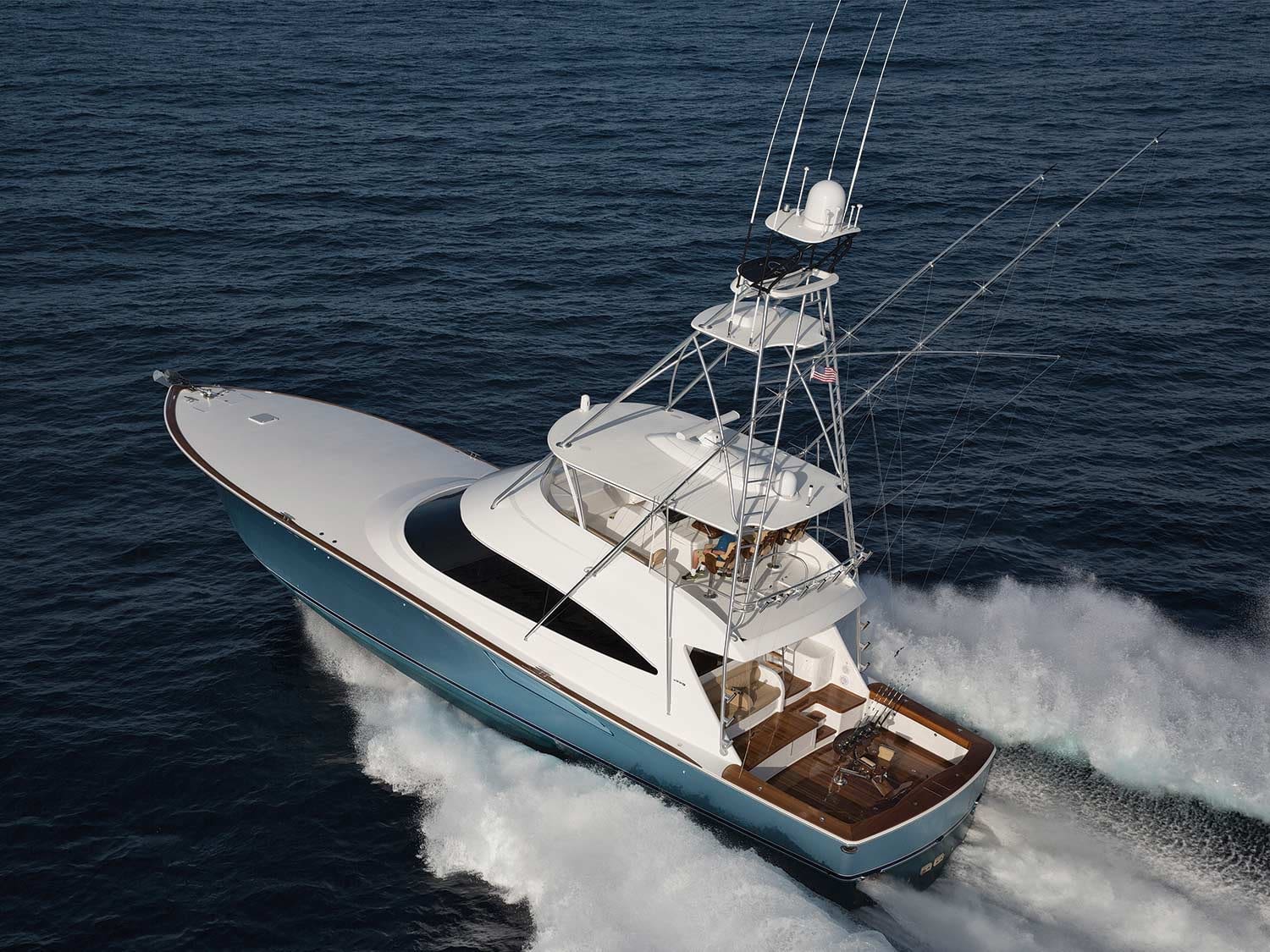
The choices are varied when deciding if your next fishing boat will sport an open flybridge with a hardtop and crystal-clear enclosure or, perhaps, you’ll opt for a climate-controlled enclosed-bridge command station instead. Although many skippers take sides when it comes to their favorite design, and for no shortage of logical as well as personal reasons, more often than not, it is the owner’s choice that finally decides the matter. Studying the purpose and accommodations of the layout provides a definite view of the benefits, attributes and limitations of each style.
The open bridge today is a far cry from its origins as simply a place to operate the boat with heightened visibility, in spite of being totally unprotected from the environmental elements of sun, wind, salt spray and rain. I recall seeing photographs of old boats from the 1940s and ‘50s with flybridges that were minimally equipped, with just a single chair, the wheel, engine controls, and wiring fed through a tube in the roof from the lower station. On the deck, a glass port offered the captain a view of the engine gauges below on the console, while the front and side bridge wings were made of canvas that was secured to metal piping screwed to the roof. Chrome-plated bronze step plates on the house sides and the piping above served as grab points, providing passage to the bridge from the cockpit. Utilitarian, yes, but that’s the way it was. These days, the flybridge has thankfully evolved (at least) tenfold, and has also enhanced what was once a simple platform with a multitude of critical features that a captain needs to do his multitasked job successfully and efficiently.

Design and Function
Operator visibility for fishing and safe navigation in all weather and sea conditions is crucial, and the helm layout on a flybridge reverts back to design and function. Running a boat might look like fun to the uninformed, but in truth, steering a 60-footer that displaces almost 100,000 pounds and cruises along at 30-plus knots is both exhilarating and tense at times due to changing ambient conditions. Undivided attention is mandatory, and a properly designed bridge is meant to help get the job done safely.
Two prevailing styles include the centerline helm station with a walkaround center-console featuring passageways forward to both port and starboard, and the peninsula design that favors passage to one side. The choice is often dictated by the size of the boat, but especially by the width and length of the deckhouse. A flybridge with wings that extend to the outmost measurements of the deckhouse will arguably offer more square footage for seating, moving about, storage and other appointments. But either way, the most important factor is that when you stand behind the wheel and operate the boat through all throttle settings, the view is unobstructed looking forward and side to side, as well as down into the cockpit below.

On larger vessels, it is not uncommon to incorporate a raised helmsman platform to boost the height of the operator for enhanced visibility forward. Savvy boatbuilders sometimes take advantage of the platform to include storage inside the shell. The amount of helm seating is a choice that needs to be decided, but the decision should take into account more than just the number of chairs. Is there sufficient room to easily access the fishing rods stowed along the aft belly rail without disturbing the operator, or a passenger who is already seated? Will a third chair crowd the access to the flybridge ladder? Is there room for grab rails or a hatch for secure movement up and down? And finally, how many people does the captain really want on the bridge anyway? Likely as few as possible.
More alternatives are conveyed in selecting the console layouts. A center-console helm can leave room for flanking lounges that also conceal storage, such as a dry space for loose gear or safety items. On long runs, the lounges are particularly inviting for relief crew to sack out. Removable backrests can be built into the lounges so occupants can stretch out and face forward while the boat is underway, or reversed to face aft, transforming the lounge into a jump seat for spotters to watch the spread. Space in front of the console can be utilized to include another lounge, a table with built-in storage, a big freezer, a refrigerated drink box, and/or a sink outfitted with a freshwater outlet and a washdown hose for rinsing salt from the enclosure for increased visibility after a long, wet run, or for spraying down the bridge area on the way back to the dock. Forward is a cavernous stowage area in the brow that often houses air horns and air-conditioning units.
The peninsula-style helm is equally functional, although the configuration of storage and lounging might be quite different. The bridge deck is wrapped in three-sided enclosure panels for visibility and weather protection, while vents in the top portion provide a fresh breeze while still protecting the bridge occupants from direct spray and rain.
Electronics take up most of the space in both of these helm layouts but do allow for maximum customization. Some consoles are designed with angled pods to flush-mount displays beneath a clear acrylic panel with other accessories, switches and controls in full view while offering the equipment protection from the elements. This arrangement generally allows sufficient access inside the console to reach wiring, connections, steering and other systems, as well as storage for bulkier items such as life jackets and throw rings. Another popular approach is to mount the electronics so they rise up from inside the console with an electric or hydraulic lift. However, this also means that the equipment is exposed to the elements while in use. To prevent engine instrumentation and other equipment from crowding the helm but still be in reach and visible, drop-down compartments or molded-in overhead pods are commonly installed in the underside of the hardtop. Teaser reels and other electronics also find homes in the hardtop directly above the captain’s chair.

Enter the Enclosed
The evolution of the open flybridge has made it a seagoing work of art that can check every box for fishing prowess on the edge—to raise, hook, and release or boat a trophy—but the constant exposure to hot and cold environments, the sound of whipping wind, sheets of spray crashing against the enclosure, engine noise, vibrations, and the banter on the VHF radio all take a toll on the captain in the form of accumulated fatigue. And while there is no denying the popularity and purposefulness of the open bridge, there might come a time when creature comforts and quiet time become sought-after issues, especially for programs whose run times to the fishing grounds are extended. It is here where the enclosed flybridge becomes a significant player.
Unlike an open-bridge design, which is truly the sum of numerous individual parts fastened together, an enclosed bridge is generally singular in form and function. The molded roof, windshield mullions and bridge superstructure become a single unit with a solid, watertight door on the bulkhead that opens out to a bridge deck to access the cockpit. The control station on the enclosed bridge is forward on the centerline, and the closest thing to the helmsman’s eyes is a solid-glass windshield that delivers uncluttered, unobstructed visibility. Electronics surround the steering wheel for easy viewing and operation, and the hardtop overhang helps to control glare and water reflections.
One of the most important accessories at the enclosed-bridge helm is a camera monitor that keeps the operator informed about conditions around and throughout the yacht. Seating options are varied, but a popular layout features an adjustable helm seat with passenger seating or lounges to port and starboard. Another endearing aspect of the enclosed bridge is the spacious area aft of the helm, which often gets tagged as a second salon with a sofa or dinette. A line of cabinetry opposite the lounge seating houses accoutrements, including refrigeration, a sink, an entertainment system and additional storage. And almost always, a staircase is installed and directly connected to the salon on the main deck.

Back when I ran an open-bridge convertible, I filled in for a friend who owned an enclosed-bridge boat to run a nighttime bluefish charter. I had plenty of experience running at night with my boat, but my first trip operating from an enclosed bridge at night was all it took to realize some of the benefits of this design. We caught plenty of fish for the charter group that evening, but I was more impressed with the quietness of the ride to and from the offshore grounds. Even the ringing 6-71 Detroits sounded well-mannered that night, and unlike my open bridge, where I was always damp with salt air and exhaust mist, I was dry, warm and comfortable. The experience left me envious, thinking of my next several Hudson Canyon trips and the one-way 75-mile jaunt from New Jersey’s Manasquan Inlet, a run that always seemed longer on the way home.
The comfort afforded by a climate-controlled enclosed bridge is unchallenged by the ride in an open-bridge boat, particularly in riotous seas or inclement weather. And without having a deck to wash, an enclosure to chamois or seat cushions to wipe down, taking care of the interior and exterior of the enclosed bridge is a snap; a quick pass with a vacuum, a microfiber cloth to wipe down the woodwork, and a generous outside rinse with Spot Zero water is usually enough to remove salt and keep the windows clear and spot-free.

Changes in Design and Strategy
Fishing from an enclosed bridge can be quite a different story than fishing from an open bridge, and it does require significant changes to your strategy. Capt. Mike Hunter of Princess Lily , a Palm Beach, Florida-based 66-foot Viking enclosed bridge, splits his time between fishing from the aft helm station on the bridge deck and from the tuna tower. With remote screens at both the aft helm and in the tower, he can monitor his electronics and operate the teaser reels trouble-free. The crew use headsets to help with back-and-forth communications between the helmsman and the cockpit, relaying and receiving information to minimize yelling and confusion. Since his bridge-deck helm is on the starboard side, Hunter likes to fight his fish in a right-hand turn because he can see the angler, the rest of the crew and the fish more clearly. And even though he can see through the aft window and through the windshield from inside the bridge, he still is concerned with the restricted view of the port side and will move around regularly to verify that no traffic is nearby. Training himself to be more cautious in looking out for small boats keeps him alert and his anglers connected to more fish. The view into the cockpit, however, is spot-on, and he can see everything at a glance and not just settle for watching the rod tips. Similarly, by looking aft when in the tower, he can observe, advise and direct his anglers to where their baits need to be. To make his top-flight work more accommodating, he also has equipped the tower pod with a removable, wraparound clear panel that extends vertically from the top of the pod to the buggy top to counter those long hours of cold northerly winds when the sailfish are biting in South Florida.
Brielle, New Jersey-based skipper Capt. Bill Sevistakis has won and placed in mid-Atlantic marlin and tuna tournaments while running a 65-foot Hatteras enclosed bridge with a tower, and a 74-foot Viking enclosed bridge with no tower. He appreciates the comfort, flexibility and convenience that the enclosed-bridge style offers more than the many open-bridge convertibles he has operated in his long career in the Northeast to the Caribbean. As a youngster in St. Croix, Jamaica, he worked with his grandfather, who fished an enclosed-bridge boat, and quickly noted the benefits of not wearing the ocean at the end of the day.

Like any design, the enclosed bridge is not without shortcomings. Sevistakis points out that storing fishing rods can be an issue because the enclosed bridge often lacks those long seating benches that are seen on open boats, while Hunter notes that the space inside the enclosed bridge can be limited when it comes to the conveniences of a full-size food or bait freezer like those typically found on big open-bridge convertibles. But both skippers do agree that on long-range trips, the enclosed platform provides the quiet comfort that many are after.
With so many excellent choices on the market from a variety of production and custom builders, the choice really hinges on how you plan to use the boat, as well as your fishing style, the prevailing local weather conditions and more. You really can’t go wrong with either design, just be sure to evaluate your needs and educate yourself of the options.
Option No. 3

Proving that the sky is indeed the limit in big enclosed-bridge convertibles, one option is installing an open flybridge above the enclosed bridge in lieu of a tuna tower. Known as a skybridge, a ladder on the aft bridge deck leads to a peninsula-style helm with pedestal seats, and a scaled-down lounge. A fiberglass hardtop and a three-sided enclosure provide weather protection in what might be called the best of both worlds—and then some.
This article originally appeared in the December 2021 print issue of Marlin.
Search here
Research & environmental, roffs™ oil & gas.
Shipping, Tow, and Rig Move Forecasts Current and Eddy Forecast Samples
Commercial Fishing Analyses
Recreational fishing analyses, recent articles.
Big Blue Marlin Dominate Final Day of the 2024 MidAtlantic

Louisiana Wildlife and Fisheries Commission Expands Shark Harvest Opportunities
Northeast U.S. Spring Preview 2024: CONDITIONS ARE WARMING UP
How to Fish for Wahoo Using Slow Trolling Speeds
- Nautical Dictionary
- Connect on WhatsApp
Bridge wing(s)
Nautical term: bridge wing(s), definition of bridge wing(s).
Bridge wing(s) refer to lateral extensions to a vessel’s bridge. These extensions enable the bridge crew to have a direct line of sight beyond the hull side. For instance, during navigation through narrow waterways, the bridge wing extensions allow the crew to maintain a clear view of the surrounding area, ensuring safe and efficient navigation.
Explore other nautical terms:
- Painting beams
- Marlinspike
- Rudder truck or case
Head back to the Nautical Dictionary
Ready for your next big adventure?
Book a tour with highlight charters today.

Take a Tour With Us!

Sunset Sailing Experience (4 Hours)

Swim, Snorkel, Paddle (4 Hours)

Whale Watching Tour (4 Hours)

Yelapa Town Waterfall Day (10 Hours)

Yelapa Town and Waterfall Overnight (2 Days)

Surf, Snorkel, Paddle (8 Hours)
Recommended reading.
Want to learn more about life on the water? Check out one of these books:

Boatowners Mechanical and Electrical Manual 4/E

Deep Shadow (The Deep Series Book 1)

Barbarian Days: A Surfing Life
- Crew Accommodation
- Crew Agencies
- Lifestyle Management & Concierge Services
- Limousines & Car Hire
- Marinas & Ports
- Maritime Lawyer
- MCA Approved Doctors
- Restaurants
- Yacht Agents
- Yacht Brokers
- Yacht Charter Companies
- Yacht Management Company
- Yacht Provisioning Companies
- Yacht Refit & Repairs
- Yacht Sales
- Yacht Training Facilities
- Yachting Equipment

BNWAS and how it affects your yacht November 5th, 2014

BNWAS and how it affects your yacht
BNWAS - Bridge Navigational Watch Alarm System is a safety system made mandatory in amendments to SOLAS (Chapter V, regulation 19). Its purpose is to monitor activity on the bridge and detect inactivity of personnel on watch and then alarm and alert the master or other qualified crew, thus avoiding a potential maritime accident.
BNWAS will affect all yachts greater than 150 GT that are built to the Large Yacht Code and the Passenger Yacht Code and must be installed on all newbuild vessels with keels laid on or after the 1st of July 2011. This equipment is considered to be part safety equipment and it will therefore be surveyed as such.
Type approved BNWAS must be fitted or retrofitted:
- To yachts of 150GT and greater and all vessels constructed as per the Passenger Yacht Code irrespective of size that are constructed after the 1st of July 2011.
- No later than the first survey after 1st of July 2012 to All Passenger Yacht Code vessels that were constructed before the 1st of July 2011.
- No later than the first survey after 1st of July 2012 to yachts of 3000GT and above that were constructed before 1st of July 2011.
- No later than the first survey after 1st of July 2013 to all yachts of 500GT and above, but less than 3000GT that were constructed before the 1st of July 2011.
- No later than the first survey after the 1st of July 2014 to all yachts of 150GT and above but less than 500GT that were constructed before the 1st of July 2011.
When installing the BNWAS to your yacht, you should consider that activating the reset must be possible without having to move from a proper lookout position. These reset buttons could therefore be located:
- At the helm or conning position.
- At the navigational station
- On the bridge wings
The size of your yachts bridge may allow you to have a single reset button covering all of the above locations but take into account that it should it should be possible to reset the BNWAS during manoeuvres without having to leave the manoeuvring station (which may be a bridge wing). The IMO has agreed that other methods are allowed to reset the BNWAS system and these may include external inputs from other equipment such as the radar or chart plotter that will register the alertness of the watchkeepr, and or certain speech recognition sensors, inputs from motion sensors or the watchperson performing a single action on a BNWAS device.
Note that it should not be possible to cancel alarms on the system outside of the areas that are considered to be the proper lookout position.
Yachts will be required to use the BNWAS whenever the vessel is underway or whenever the ships heading or track control system is engaged, unless inhibited by the master. Although most BNWAS are equipped with an automatic mode allowing it to be automatically activated when the autopilot is on, this mode is not considered to meet the requirements of the IMO and so operation in this mode should be avoided.
When the BNWAS goes into alarm because it has not been reset by the duty watch person, the 2nd alarm is to sound in bridge officers cabin or the masters cabin after 15 seconds of the failed resetting by the watch person. The second alarm sounder can be located and selected between numerous cabin, but it must not be possible to isolate the alarm to the selected cabin/s.
If the second alarm is not reset within 90 seconds, the third alarm must sound to further crew and this can (but not necessarily) be performed through the general alarm.
For further reading, please reference your SOLAS manual, chapter 5, regulation 19 and the MCA Large Commercial Yacht Code (LY3) .
- News & Trends
- Water, Electricity
- Yacht control panel
- Cramm Yachting Systems BV
Exhibitions
Yacht control panel bow stern touch screen.

Characteristics
Description.
Meet this supplier at the following exhibition(s):
19-21 Nov 2024 Amsterdam (Netherlands) Hall 09 - Stand 209
- Yacht monitoring and control panel
- Touch screen monitoring panel
Boarding Passerelles
Cramm passerelles are the perfect, safe and quick system for boarding your superyacht. Our passerelles are designed to perfection, providing you with an elegant and timeless entrance for your guests and crew.
You can select from a wide range of standard modular solutions or fully-customised boarding equipment to meet your wishes and demands. For both options, we use the best available materials, deliver total service and assistance during the entire project, and guarantee maximum safety while operating.
Accommodation Ladders
Cramm boarding ladders are the perfect, safe and quick solution for boarding your superyacht. Our ladders are designed to perfection, providing you with an elegant and timeless entrance for your guests and crew.
You can select from a wide range of standard modular products or a fully customised boarding ladder to meet your wishes and demands. For both options, we use the best available materials, deliver total service and assistance during the entire project and guarantee maximum safety while operating.
Deck Cranes
Cramm deck cranes are the ideal cranes to hoist your equipment such as tenders, jet skis and submarines to and from your super yacht. Our cranes offer maximum efficiency in that they can be used for cargo handling applications as well as rescue boat and life raft hoisting.
Depending on your requirements and ideas, Cramm can supply a crane to match every need. For example, an impressive project we completed was a custom-made deck crane with a hoisting capacity of SWL 15 tonnes and a teak gangway on top.
Sliding Beam Cranes
Our overhead sliding beam cranes are designed to lift equipment such as tenders, rescue boats, life rafts, jet skis, submarines and cars safely and easily in and out of the superyacht. Cramm’s range of overhead cranes includes various types from single-sided and parallel set-up to outward telescopic.
We have also developed a special type of sliding beam crane for lowering items into the water to port and starboard. The development of special profiles for all our sliding beam cranes ensures that every crane has a minimum height, a key benefit compared with many other sliding beam cranes on the market.
Doors and Hatches
Opening up the side of the yacht offers a huge amount of additional possibilities to the yacht, such as tender storage, beach clubs and others. The design of the yacht door is based on a 3D model of the client’s yacht, and custom-made in aluminium, steel or stainless steel.
The main difference between a door and a hatch is that a door is located vertically while a hatch is located horizontally. The outside of the doors follows the shape of the hull, while the inside is level and straight. The doors can be electric or hydraulically driven and opened horizontally or vertically to give maximum flexibility.
Heligrid Landing Platform
The Cramm helicopter landing grid system, combined with a harpoon rapid securing system, aims to secure a helicopter to the flight deck immediately on touchdown by engaging and locking the helicopter harpoon on to a landing grid in the flight deck.
Satisfying the most stringent NATO Stanag 1276 requirements, the system can be used for various types of helicopters, including defence and rescue helicopters. It prevents movement of the helicopter on the flight deck under the influence of large waves and strong side winds, and allows the helicopter to land and take off safely while at sea.
Balconies and Platforms
Yacht platforms and balconies are ideal elements to expand the exterior space and connect it with the interior, providing easy water access and space to enjoy the view. The platforms or balconies can be equipped with many features, creating a luxury outdoor living space close to the water.
Such platforms, also known as beach clubs, compensate for the lack of easy water access and offer the client options such as swimming, sunbathing and scuba diving directly from the yacht. We provide customised folding and/or sliding systems integrated into the vessel’s hull or superstructure.
Telescopic Masts
Cramm can supply all your requirements regarding navigation masts, antenna masts, flag masts or light masts. Cramm telescopic masts have many advantages over standard masts. When the telescopic mast is retracted into the deck, it gives the deck that superyacht sleek and luxury look.
Cramm masts are manufactured from stainless steel, with visible components receiving an elegant brushed finish. If preferred, the whole mast can be faired and painted in the same quality paint as the yacht, to give it that extra designer look.
Bridge Wing Stations
When morring the superyacht, the captain cannot always oversee the situation from the bridge which can result in dangerous situations. Bridge wing control stations offer that extra visibility and overview of the situation to create maximum safety when docking.
The return on investment of using a wing control station can be significant. Preventing one accident during the lifetime of the superyacht will generally cover the cost of the wing control station.
Boat booms are located on the side of the yacht and are used while a superyacht is anchored to attach smaller boats and tenders on the yacht. This prevents that the smaller boats or tenders can hit the yacht. Boat booms are fully automatic and can be controlled by means of a push-button-panel or a radio remote control.
The boat booms are usually placed near a tender garage or boarding platform. They are non, single or double telescopic systems depending on the requested reach and available storage length. Boat booms can be delivered with a box/trunk for welding in the yacht structure.
Wärtsilä Nacos Platinum bridge systems selected for two new mega yachts

The technology group Wärtsilä has been contracted to supply its Nacos Platinum integrated bridge system for two new mega yachts; one an 85 metre long vessel and the other 91 metres long, being built in Greece. In addition to the systems, Wärtsilä will also provide the project management, engineering, pre-wiring of the consoles and system commissioning services, thus delivering a complete solution. The orders with Wärtsilä were booked in March and July 2017.
The new and advanced bridge console concept for these vessels includes an integrated navigation system (INS) with compass and latest technology navigation sensors, and an integrated automation system with power management functionality. A state-of-the-art propulsion control system and a radio communication system are also included. The overall bridge design has been customised according to the specific requirements for these yachts.
“The Nacos Platinum integrated system is based on the very latest technologies and is in accordance with known and anticipated rules and regulations. Furthermore the system is supported throughout the entire lifecycle to ensure long-term usability and to provide real customer value. Throughout these project negotiations we have worked closely with our local sales and service partner, Environmental Protection Engineering located in Piraeus, and their cooperation has been much appreciated,” says Maik Stoevhase, Director, Automation, Navigation and Control & Integrated Systems, Wärtsilä Marine Solutions.
The modular bridge concept hosts Multipilot multi-functional work stations for indicating the network radars, the electronic chart display and information system (ECDIS), conning, and the integrated automation on the main console. On both bridge wing stations, Datapilot screens will be installed. The enhanced software features of the Nacos Platinum system are designed to promote vessel safety, especially when sailing in unfamiliar waters.
A large 46 inch ECDIS work station will be installed in an adjacent ship office for navigational voyage planning and crew briefing purposes. The system will be connected to the Nacos digital data network enabling planned routing to be accessible from the bridge work stations via an integrated Trackpilot system.
Wärtsilä’s extensive offering for the luxury yacht market, including the Nacos Platinum system, can be seen at stand QS 88 at the Monaco Yacht Show, being held from September 27 to 30.
Link to images Caption: State-of-the-art navigation consoles are included in the complete bridge system.
Media contacts:
Mr Bernhard Jungsthöfel Sales Engineer, Electrical & Automation Wärtsilä Marine Solutions Tel: +49 4088 2522 87 [email protected]
Ms Marit Holmlund-Sund Senior Manager Marketing, Communications, Marine Solutions Wärtsilä Corporation Tel: +358 10 709 1439 [email protected]
Wärtsilä in brief: Wärtsilä is a global leader in advanced technologies and complete lifecycle solutions for the marine and energy markets. By emphasising sustainable innovation and total efficiency, Wärtsilä maximises the environmental and economic performance of the vessels and power plants of its customers. In 2016, Wärtsilä's net sales totalled EUR 4.8 billion with approximately 18,000 employees. The company has operations in over 200 locations in more than 70 countries around the world. Wärtsilä is listed on Nasdaq Helsinki. www.wartsila.com

- Privacy notice
- Cookie notice
- Terms of Use
REQUEST MORE INFO
" * " indicates required fields
NORDHAVN 68 FORWARD PILOTHOUSE
Nordhavn 68 forward pilothouse.
It’s big, handsome and seaworthy.
With plenty of living room, a long list of comfort and convenience features and the range and size to cross oceans, the Nordhavn 64/68 series has proven a popular trawler size, bridging the gap between the Nordhavn 55 and the larger Nordhavn 76. Built on the same extended hull as the aft pilothouse Nordhavn 68, the new forward pilothouse version retains the same interior layout as the Nordhavn 64, but adds four feet (1.2 meters) of length to the aft cockpit, increasing the outdoor living (and playing) space to 191 square feet (17.7 square meters). An additional benefit—one that’s always appreciated— is a larger lazarette. Compared to the Nordhavn 64, the N68 forward pilothouse enjoys the advantage of a slight increase in cruising efficiency because of its longer waterline. Compared to the Nordhavn 64, the N68 forward pilothouse enjoys the advantage of a slight increase in cruising efficiency because of its longer waterline. Compared with its aft pilothouse sibling, the forward pilothouse version has a slightly larger fuel capacity at 3,230/12,226 L versus 3,136 gallons/11,871 L for the aft pilothouse version.
Living on one level
The saloon, galley, cabins and machinery spaces in the Nordhavn 68 forward pilothouse are the same size and layout as the Nordhavn 64. It’s an arrangement that some people prefer over the aft pilothouse version. “In this layout, the advantage is you get the owner’s cabin closer to the middle of the boat,” points out Jeff Leishman, the Nordhavn 68’s designer and chief designer for Pacific Asian Enterprises. A cabin closer to the boat’s geometric center sees less motion and is therefore more comfortable at sea and at anchor. Also, since the cabin is located in a wider part of the boat, it’s roomier. The teak or cherry joinery used in the master and guest cabins, and throughout the yacht, reflects PAE’s high standards of workmanship. The head for the owner’s cabin features a tile floor, granite countertops and a teak vanity. The other big advantage the Nordhavn 68 forward pilothouse shares with the 64 is that the two guest cabins are on the same level as the living spaces—the galley and saloon. So, less time is spent climbing up and down stairs—climbing stairs can be a burden for older guests. Having the guest cabins just a few paces away from the owner’s cabin is also an advantage if a family lives on the boat and the cabins are occupied by children. The starboard cabin is equipped with bunks or twin beds and the port cabin has a queen-size bed. The guest head and shower are in the bow. Finished in teak, with granite countertops and a tile floor, it is accessible by doors in each cabin.
Saloon and galley
The roomy saloon, at 11 feet 3 inches by 17 feet (3.4 meters by 5.1 meters), retains the same space as the Nordhavn 64. To maximize living space, the saloon extends the full beam of the yacht on the port side. An 18-inch-wide (45 centimeters) walkway leading from the cockpit to the pilothouse and foredeck is on the starboard side, however a dual-walkway version can be ordered. There are two seating areas in the saloon with settees and tables, as well as a large lounge chair. Varnished teak or cherry wood paneling, premium carpeting and upholstery and soft overhead lighting make the Nordhavn 68’s saloon a relaxing place to spend time on a passage. The four 26- inch (66 centimeters) by 42-inch (106 centimeters), half-inch thick (1.2 centimeters) tempered windows afford an outstanding view of the changing scenery outside. Like all good sea boats, handholds are strategically placed throughout the living area. The 21-square-foot (1.9 square meters) galley adjacent to the saloon is fully equipped with first-rate appliances, including a Sub-Zero side-by-side refrigerator/freezer, and GE cook top and stainless steel convection wall oven. There are two additional GE freezers located in the utility room. The bull-nosed countertops are granite in the owner’s choice of colors.
Seagoing pilothouse
Up a short flight of stairs from the saloon and galley is the Nordhavn 68’s pilothouse. Though not as large as the aft pilothouse version, its location amidships, where motion is minimal, is another advantage it enjoys. The pilothouse measures a spacious 14 feet (4.2 meters) by 18 feet (5.4 meters), with a generous 6 feet 9 inches (two meters) of headroom. Paneled in varnished teak or cherry, it has a settee and table, double pilot berth where the off-watch can be close at hand during night passages or in inclement weather, and numerous cupboards, drawers, lockers and bookcases. It makes a great guest cabin when in port. Eleven half-inch thick (1.2 centimeters) tempered-glass windows offer a commanding view in all directions. The helm station features two Stidd slimline chairs, an instrument console 6 feet 8 inches (2.03 meters) wide, with plenty of room for instruments, gauges and controls, and a 30-inch (76 centimeters) destroyer wheel.
Portuguese bridge and foredeck
Heavy-duty Dutch doors on either side of the pilothouse open onto the Portuguese bridge and boat deck. Another Nordhavn trademark and a necessity on a seagoing boat, the Portuguese bridge provides added security when one needs to step outside in rough weather. The boat deck’s location, up high and aft of the pilothouse, affords more protection in rough weather for the yacht’s tender than the aft pilothouse 68 offers. When it’s time to place the tender in the water, the davit will set it down next to the cockpit at the aft of the yacht, where it is easily boarded via boarding doors in the cockpit bulwarks, or from the swim platform. And when it’s time to tie up or cast off, skippers will find it’s a shorter run to the foredeck from the pilothouse’s mid-ship location. Control stations with thruster and engine controls, located on the port and starboard ends of the Portuguese bridge and in the aft cockpit, take much of the drama out of docking and undocking. A set of steps provides access to the boat deck from the cockpit. The foredeck extends for 16 feet (4.8 meters) beyond the Portuguese bridge. Twelve-inch high (30 centimeters) bulwarks topped with 30-inch high stainless steel railings extending all the way to the bow, ensure a secure working environment. The stainless steel double bow roller holds a 300-pound (136 kilograms) Airtex anchor on 400 feet (121 meters) of half-inch, high-tensile chain. A Maxwell hydraulic windlass, with two control stations, easily handles anchor retrieval. There is even a high-pressure wash-down system to get all the gunk and mud off the chain before it comes aboard. A nice touch that virtually eliminates the onerous task of occasionally emptying the chain locker and unplugging a drain clogged by muck.
Flying bridge with a view
When the weather is nice, skippers will want to conn the boat from the flying bridge. Sitting a commanding 15 feet (4.5 meters) above the water, it is easily accessed using a stainless steel ladder on the boat deck or by steps leading directly from inside the pilothouse. The flying bridge is equipped with a full set of instruments and controls. A U-shaped fiberglass settee aft of the helm has seating for four around a teak table. There is also a wet bar and a Norcold refrigerator. This will probably be a nice place to hang out and share a sundowner.
Utility room and laundry
Stairs forward of the galley and saloon lead to the utility/laundry room—another feature missing in the aft pilothouse Nordhavn 68. Countertops, with drawers below and cabinets above, surround three sides of the utility room, and two GE freezers and Bosch combination washer/dryer are located there. There is also a day head. The utility room can also be ordered as a crew cabin, with two bunks (the lower one a double), a teakfaced closet, drawers and a shower.
Ample room for machinery
The utility room leads to the engine room through an insulated, watertight door. With 192 square feet (17.8 square meters) there is ample working space. Motive power for the yacht comes from a 425-horsepower, John Deere diesel engine turning a 42- inch (106 centimeters) propeller via a 3.5-inch (8.8 centimeters) Aquamet shaft and a Twin Disc transmission with a 3:43:1 reduction gear. A keel cooler and dry exhaust are standard. Steering is handled by a Kobelt hydraulic steering system, while ABT digital stabilizers keep everything on an even keel. The 38-horsepower hydraulic bow and stern thrusters make maneuvering in tight quarters a snap. The engine room also houses a Lugger L1066 diesel wing engine, with its own prop shaft, folding prop, fuel and cooling system, as well as the generator and an optional Village Marine Tec watermaker. Two 250-amp, 24-volt hydraulically driven alternators supply electricity for the yacht’s various systems, and an additional 25-kilowatt Northern Lights generator supplies power for AC consumers such as the stove, refrigerator, freezers, air conditioning and the washer/ dryer. Shore power comes aboard via two 50-amp 240-volt receptacles and a 30-amp 120-volt receptacle. Two Glendinning shore power cord retrieval systems are also standard. Battery power is supplied by twelve 225-amp Lifeline 8D AGM house batteries. Two 4,000-watt inverter/chargers handle battery charging. Although it is considered a production boat, PAE will modify the yacht during construction to accommodate the buyer’s wishes; however, there’s not much to add other than personal items, bedding and provisions. The Nordhavn 68 comes fully equipped—flying bridge, wing engine, generator, air conditioning, stabilizers, davit, appliances, even the plasma TV are standard. With so much to offer, there is no doubt the new Nordhavn 68 forward pilothouse, like its predecessor the Nordhavn 64, will be one of the most popular boats in the Nordhavn fleet. More capability, comfort and range can only make it better.
N68 Quick Specs
| LOA: | 68' / 20.73 M |
| LWL: | 63' 2" / 19.25 M |
| BEAM: | 20' 4" / 6.20 M |
| DRAFT: | 7' 2" / 2.18 M |
| DISPL.: | 205,000 lbs. / 92.99 MT (full load) |
Running/Exterior Gallery
Interior gallery, specifications.
| LOA: | 68′ / 20.73 M |
| LWL: | 63′ 2″ / 19.25 M |
| BEAM: | 20′ 4″ / 6.20 M |
| DRAFT: | 7′ 2″ / 2.18 M |
| DISPL.: | 205,000 lbs. / 92.99 MT (full load) |
| FUEL CAPACITY: | 3,136 US gals. / 11,871 L |
| WATER CAPACITY: | 673 US gals. / 2,548 L |
| HOLDING TANK CAPACITY: | 150 US gals. / 568 L |
| GRAY WATER TANK CAPACITY: | 150 US gals. / 568 L |
Hull lamination schedule per construction plan. The area below water line to use “Isophthalic” gelcoat and vinylester resin for the first three (3) layers. The hull lamination will use “Combomat” in lieu of standard M+WR. Deck lamination schedule per construction plan. “Cymax” fiberglass will be used for all deck lamination.
Standard gelcoat colors from Arocoat and CCP color chart. Gelcoat for deck and superstructure to be Ferro brand “Ultra” white
Hull – Arocoat gray # 340
Deck and deck house – Ferro “Ultra” white
Boot top – Arocoat dark blue # 348
Non-skid: Arocoat – light gray, to match CCP color chart # A110
Exhaust stack/flybridge – Ferro “Ultra” White
Cabin side (vertical surfaces): Klegecell # R75 varying degrees of thickness
Cabin top and deck (horizontal surfaces): Baltec or equivalent vertical end grain balsa, 1″ (2.54 cm) thick
Hull: Solid series of laminates
Deck/hull joint:
Between deck and hull flange: 3M 5200
Inside of joint: Three (3) layers M. & W.R. (where accessible)
Mechanical fastening: 3/8″ (9.5 mm) x 14 thru-bolt on 8″ (20.3 cm) centers
Teak cap: Across stern only, varnished
Longitudinal Stringer:
Hull: Seven (7) full length each port and starboard (total of 14), engine beds and floor stringers
Interior floors: per std interior layout
Ballast: Approx. 11,000 lbs (4990 kg) lead fixed per machinery layout drawing
Main Engine: John Deere 6135AFM75, M2 with continuous duty rating of 425 hp @ 1900 rpm, keel cooled with dry exhaust & 24 volt starting
Gear Box: Twin Disc # 5114, with 3.43:1 electric shift, electric clutched ‘C’ PTO
Engine Instrument Panels: Murphy PowerView, six (6) start/stop locations total
Alternators: Two (2) 175 amp 24 volt DC belt driven
Engine Controls: Twin Disc Electronic controls, six (6) stations: wheel house, fly bridge and aft deck, port and starboard Portuguese bridge and engine room
Racor crank vent and air cleaner system
Two (2) 4D batteries connected in series for 24 volt start
Engine bed to have 3/16” (4.7 mm) stainless steel cap
Stainless steel rail around engine
Engine mounted on (4) vibration Isolator Polyflex mounts
Fuel Filter: One (1) Racor 75-900MAC duplex with 2 micron filter elements in addition to secondary engine mounted filter
Propeller: 4-Blade Hungshen “Silent” to be highest quality available 44” x 34.5” (111.76cm x 87.63 cm) – left hand rotation
Propeller Shaft: A22HT 3-1/2″ (8.9 cm) diameter
Taper details: Standard SAE
Spurs line cutter on main engine shaft
Stern tube: FRP
Bearing: Rubber cutlass type at aft end
Stuffing Box: Bronze-traditional
Use “T” bolt clamps in lieu of hose clamps at the stuffing box
Keel Cooler
Jacket water circuit: R.W. Fernstrum # D1281U-E1
Engine cooling system to be filled with John Deere specified mixture of coolant/antifreeze
Engine room floors: All engine room floors and structural members to be FRP with white gel coated surfaces
Noise Control
Hull Damping – Area above the propeller rotation plane to be treated with two (2) layers of E-A-R Specialty Composites Isodamp CN Tiles (CN-62), alternating between resin and chopped glass to form a constrained layer damping system to be the inboard side of the shell plate. Installed as per figure 1
Engine room ceiling and fwd bulkhead treated with “Thinsulate”. Inboard tank sides, aft bulkhead, underside of deck, forward side of engine room bulkhead and ventilation ducts to be treated with “Thinsulate” and covered with white aluminum panels. See standard interior drawing for interior bulkhead locations treated with “Thinsulate”
Salon/galley cabin sole to have 2″ (5.08 cm) Nida Core” core system and 1/4″ (.6 cm) “decoupler” layer
Engine room hatches to have rubber gasket and lock down mechanism
Soundown Quiet Pro lining covering engine room intake and exhaust ventilating ducts, 1” (2.5 cm) thick secured with epoxy and mechanical fasteners
Insulated bulkheads in living areas using 1″ (2.5 cm) thick 3M “Thinsulate” between panels
Engine Room Ventilation: (See Air Conditioning Systems and Ventilation Systems)
Dry exhaust system: 6″ (15.2 cm) I.D.
Muffler 6″ (15.2 cm) I.D. with 6″ (15.2 cm) inlet flange and 8″ (20.3 cm) outlet flange. Inlet flange to be welded on – # TXS60TRS020
Custom exhaust blanket for engine room portion of exhaust
Exhaust piping under blanket is to be wrapped first with fiberglass tape
Stainless steel wrinkle belly sections per design
Soft mounted with Soundown mounts and spring hanger mounts per design
Wing engine: John Deere 4045TFM75, HE, 24volt, rated 135 @ 2600
“V” drive Hurth marine gear 2.477:1 ratio
Heat exchanger cooled
Shaft: 1-3/4″ (4.4 cm) diameter shaft A22HT
Spurs line cutter on wing engine shaft
Gori 3-blade folding propeller
50amp, 24 volt alternator
Twin Disc electronic controls dual station
Electronic front PTO 24 volt to operate hydraulics
Two (2) “Group 31” batteries in series for 24 volt start
20 gallon (75.7 Liter) day tank per PAE design
Racor 900 MA fuel filter with 2 micron filter element in addition to engine mounted filter between day tank and engine
Dual station panels, wheelhouse and flybridge. Also includes one “Power View” Murphy gauge
Engine bed to have 3/16″ (4.7 mm) thick stainless steel cap
5″ (12.7 cm) Centek exhaust check valve
Onan # MDKBT 27.5 KW 120/240 volt AC 60 Hz, 1800 RPM. Includes sound enclosure
Wet exhaust system using gen-sep
24 volt start
Alternator: 20 amp
ABT hydraulic system
38 hp bow and stern thrusters using 12″ (30.4 cm) tunnels with proportional controls at five (5) stations
Hydraulically powered anchor wash pump – 180 gallons (681 Liters) per minute
Hydraulically powered 180 gallons (681 Liters) per minute emergency bilge pump with manifold system and plumbing to four (4) bilge areas
TRAC # 300 digital stabilizer system with 12 sq. ft. (30.4 sq cm) fins, kelp deflectors and dual station control. Fin winglets not included. System is without winglet assembly.
Maxwell VWC 4500 windlasses with dual station controls x one (1)
Hydraulics will be cooled by hydraulic cooling pump through heat exchanger
Vise in engine room at work bench
Number and capacity: Two (2) totaling 500 gallons (1,893 liters)
Material: Integral fiberglass with vinylester resin and FDA approved gel coated interior
Inspection plates: Appropriately positioned and sized for access
Tank air tested to 4.5 lbs. (2.04 kg) per sq. inch
Tank has “Wema” level gauge
Tank baffles is spaced on 24″ (61 cm) centers as shown in design – and removable for interior access
Exterior of tank finished in blue gel coat
Tank complies with ABYC section H-23 for potable water systems for use on boats
Cleanliness: Tank interior surfaces are thoroughly vacuumed and wiped down prior to final closure
Number and capacity: Four (4) totaling 3,230 gallons (12,226 liters) with one centerline aluminum “Supply Reservoir” at 80 gallons (302.83 liters)
FRP construction from male molds using Vinylester resin. To comply with all ABYC codes for diesel fuel tanks. Tanks to be coated with fire retardant gelcoat on outside to comply with ABYC section H-33.20 for fire resistance
Inspection plates appropriately positioned for interior access by average size man. Plates to be fitted with labels that contain all information as stated in ABYC section H-33.16.3. Each internal baffle to have a removable panel to allow access to entire interior of all fuel tanks
Fuel system to include a powder coated aluminum supply reservoir, which feeds by gravity from all fuel tanks. Bottom part of reservoir to be fitted with a drain valve at the bottom of the reservoir for water and debris purging and with a water sensor – illuminating a light and audible alarm in wheelhouse if excessive water is present. Reservoir fitted with five (5) draw spigots for main, two (2) generators, wing engine and spare – mounted at lower level of reservoir but above water sensing probe. All returns from main, wing and generator plumbed into reservoir via a return manifold
Sight gauges provided for two (2) engine room fuel tanks. Forward tanks share one (1) sight gauge located in utility room
Each tank to be air tested to 4.5 lbs (2.04 kg) per square inch
Provide baffles on 24″ (61 cm) centers
Transfer manifold and 24 volt DC Orberdorfer gear pump 3.5 gallons (11.36 liters) per minute fuel pump with timer switch and Racor 1000 fuel filter with 10 micron element which can transfer fuel from one tank to another and scrub fuel while transferring. Transfer is also used to fill top part of supply reservoir for consumption testing when main fuel tank level drops below the level of the testing part of the reservoir
Exterior of tanks finished in red gel coat
Cleanliness: tank interior surfaces to be vacuumed and wiped clean before final closure
Each tank to have two (2) 1” (2.5 cm) I.D. vent lines
Each tank to have separate 2” (5.08 cm) I.D. fill pipe located a minimum distance of 18” (45.7 cm) from any ventilation openings
All hardware that comes in contact with fuel to be bonded into the 24 volt DC ground system
Fuel Pipe and Hose
Supply lines from tanks to supply reservoir are 1-1/2” (3.8 cm) I.D .with Aeroquip brand fuel hose and swaged brass fittings
Fuel line from supply reservoir to main engine filter is 3/4″ (1.9 cm) I.D. with Aeroquip brand fuel hose and swaged brass fittings
Fuel lines from supply reservoir to optional generator and wing engine to be 1/2” (1.27 cm) I.D. with Aeroquip brand fuel hose and swaged fittings
Vent lines to be fuel certified, reinforced hose 1” (2.5 cm) I.D.
Water Hoses
Cold water: Hose from water tanks to water pump and to accumulator to be 1″ (2.5 cm) diameter reinforced and approved for potable water; Branch lines to be 1/2″ (1.27 cm) Shurflo “Shurpex” brand semi rigid tubing with quick connect fittings (blue)
Hot water: Reinforced 1/2″ (1.27 cm) Shurflo “Shurpex” brand semi rigid tubing with quick connect fittings (red)
Sea water hoses: Reinforced for marine use and provided with double stainless steel clamps below the water line
All hoses used shall meet the requirements for service as set out by ABYC for the system intended
Hot Water Heater System:
Heater: Torrid with heat exchanger and single 240vac element
Thru Hulls: Bronze body, stainless steel balls and Teflon seats
Grounding wire: # 6 gauge green wire
Each thru hull to have a clearly visible tag indicating use
Each thru hull to be easily accessible
Fresh Water System:
Main Pump: Headhunter Mach 5 # M5-115 – 120 volt with pressure regulator and Groco WSA-1000 strainer on pump inlet
Groco # PST5 accumulator tank with pressure gauge
Hose from water tanks to water pumps and to accumulator to be 1″ (2.5 cm) diameter reinforced and approved for potable water
Back up pump: Headhunter “X-Caliber” 12-24 volt DC pump # XR-124
Filter: US water filter housing with a 5 micron sediment filter installed downstream of fresh water discharge manifold
Pump selection manifolds x two (2): Pump inlet and discharge manifolds made of stainless steel standard pipe. Supply manifold furnished with isolation ball valves from each fresh water tank, to each fresh water pump, and from the water maker. Discharge manifold furnished with isolation valves from each pump
Plumbing fixtures
Head sinks: Owner’s, guest, and day head. Under counter mount- HCG L 337 White oval sink. (3 total)
Galley sink: Double stainless steel Kohler # K-3351
Head faucets: Grohe # 33413 chrome (3 total)
Galley, flybridge and engine room sink faucets: Grohe # 33939 1 B0 chrome/black (3 total)
Aft deck faucet is folding faucet. Scandvik # MR4550
Engine room sink, flybridge and aft deck sink: local made stainless steel
Shower fixtures: Two (2) All Grohe # 28179 handle, # 28786 soap dish, # 28.820 24″ (61 cm) shower bar, # 28.151 hose, # 34.436 thermostat valve
Bilge Pumps:
Electric: Four (4) Par Jabsco 34600-0010 24 volt 10.8 gallons (40.9 liters) per minute. Diaphragm 1″ (2.5 cm) diameter ports, with “Ultra Senior” 24 volt auto float switch # UPS-01-24/32. One (1) in each water tight compartment
Manual: Four (4) Edson # 638AL. One (1) in each water tight compartment
Hydraulic drive emergency pump: One (1) “Pacer” 180 gallons (681.4 liters) per minute plumbed to all water tight compartments. Manifold for emergency pump to be located in easily accessible location
High water bilge pump system – engine room: Rule 16A, 3700 gallons (14,006 liters) per hour, 24 volts AC, Rule # 33AL high wate bilge alarm, and “Ultra Senior” bilge switch
High water bilge alarm panel – pilothouse per PAE design. High water bilge sense will come from standard. Ultra Senior in each bilge compartment. Visual and audio alarm panel in pilot house
Toilets and Holding Tank System:
All toilets to be Tecma Silence Plus (white). (3 total)
Water supply to toilets to be fresh water only
Holding Tank: One (1) Integral FRP with vinylester resin 150 gallon (567.8 liter) holding tank
Use only PVC pipe or Sealand “Odor Safe” hose
Holding tank overboard pumps: Edson “Bone Dry” # 120ELB 20 gallons (75.71 liters) per minute, 120 volt AC electric and Edson “Bone Dry” # 557BR 20 gallons (75.7 liters) per minute manual pump per drawing
Holding tank vent to use Sealand # 310002 vent filter
Deck fitting for portable evacuation facility
Holding Tank Level Monitor: Sealand 24 volt Tank Watch 4 panel and cap with vent, 45″ (114.3 cm) probes # 600115, including universal flange 3″ (7.6 cm) NPT with gasket and stainless steel hardware, 24 volt “Do Not Flush” status panel # 700024 and shut down relay # 342490 warning system at each toilet
Fresh water outlets on the foredeck, aft deck, boat deck and one (1) in engine room using stainless steel “Scandvik” spigot
Gray Water System:
Tank: One (1) Integral FRP 150 gallon (567.8 liter) tank. All sinks, showers, and air conditioning condensate to drain to tank. All drains to have “P” traps and sloped downhill run to tank. Exception: engine room sink drain will be pumped to gray water tank . Tank equipped with electric and manual discharge pumps, level switch for pump starting, and level monitor system
Electric Discharge Pump: Sealand T24 discharge pump 24 volt with auto/manual switching. Pump inlet to draw within 1″ (2.5 cm) of the absolute bottom of the tank. Pump to discharge overboard through anti siphon loop
Level Switch: ULTRA Junior pump switch (float type) Model WPS-02-24/32, 24 volt to auto start and stop the gray water pump in the AUTO mode. In AUTO mode, switch to start pump at 2-1/2″ (6.4 cm) depth and stop pump at 1″ (2.5 cm) depth
Level Monitor System: Headhunter 24 volt tank sentry panel WPS-1500
Manual back up pump: Edson # 638AL
Fitting provided for deck pump out.
“Hepvo” odor valve fitted on grey water system
“Scandvik” aft deck shower installed on transom per PAE design
LPG system with two (2) 30 lb. (13.6 kg) aluminum LPG bottles with “Trident” two stage regulator and “Xintex” monitor panel # XINTX#S-2A with two (2) sniffers located per PAE design
Raw water supply to various systems: Individual raw water inlet thru hulls per item requiring raw water
Wing engine, generator(s), water maker intake and air conditioning
Each inlet to have Groco strainer
Each thru hull on the exterior to have grate installed to keep debris out
Oil Change System
System utilizes a 120 volt AC Orberdorfer gear pump, 3.5 gallons (13.25 liters) per minute to drain and fill engine lube oil from/to crankcases of main, wing, and generator(s) engines. Pump is controlled by a three (3) position switch mounted at pump location. Switch positions to be labeled “ENGINE OIL DRAIN”, “OFF”, “ENGINE OIL FILL”
Oil change manifold per PAE design. Manifold, pump and control switch to be located in an accessible and comfortable location. Engine side of manifold to include isolation valves for each engine. Pump discharge/fill side to include a hose of suitable length for drawing from and discharging to a locally placed container
Engine room sink sump system
System to be self contained with external whale gulper pump and Ultra senior float switch consisting of sump enclosure, sump pump and float switch
Sump pump to discharge to the gray water tank.
A.C. Electrical System: Vessel is fitted with two (2) 240 volt AC. House shore power is fed through a 12KVA isolation transformer. Current is distributed through custom PAE electrical panels containing 240 volt AC and 120 volt AC sections, volt and amp meters and individual breakers for functions
Two (2) Outback # VFX3524 3.5 kW 24 volt battery charger/inverters with remote control panels. Inverters are installed in a “series/stack” configuration enabling the vessel to have 120 volt AC and 240 volt AC inverted power. Electrical panel is fitted with an inverter bypass switch in the event of failure
AC Outlets are standard US format in black 120 volt AC. Location shown on drawing
All outlets in head compartment and galley are GFCI type in black
All external outlets have water proof covers
Two (2) Glendinning shore power cord retrieval systems with barrels located in the transom. One (1) each for the 240 volt house shore power and air conditioning shore power. Each system to be provided with 85′ (25.9 m) of useable shore power cable from the transom
Standard shore power inlets located on the port side of foredeck
D.C. Electrical System is provided by 24 volt DC and 12 volt DC systems. The primary DC system is 24 volts and the secondary system is 12 volts for any equipment that is only available in 12 volts
Standard batteries are located per PAE machinery drawing and are provided as follows:
24 volt DC house battery bank – consists of twelve (12) 8D, 12 volt “Lifeline” AGM @ 255 Ah each. Two (2) groups of six (6) batteries each are connected in parallel. The two groups are connected in series to provide a total battery bank rating of 1,530 amps at 24 volt. Includes Link 10 battery monitor
12 volt DC power is supplied to the pilot house distribution panel by one (1) Group 31 “Lifeline” AGM @ 105 Ah battery. A Xantrex 12 volt DC 20 amp three bank output battery charger charges the batteries through the inverter
Main engine starting – two (2) 4D “Lifeline” AGM @ 255 Ah each connected in series for 24 volt starting. Switching logic to parallel with 24 volt house bank for emergency starting
Generator starting – two (2) Group 31 “Lifeline” AGM @ 105 Ah each connected in series for 24 volt starting. Switching logic to parallel with 24 volt house bank for emergency starting
Wing engine starting – two (2) Group 31 “Lifeline” AGM @ 105 Ah each connected in series for 24 volt starting. Switching logic to parallel with 24 volt house bank for emergency starting
24 volt battery charging is provided in the following ways:
Outback inverter/chargers provide a total of 170 DC charging amps at 24 volts
One (1) “Skylla” 100 amp charger – TG 24/100 (1+1), part number SDTG2401003. This charger is a back up to the inverter/charger and serves as a battery charger when the vessel is in a 50 Hz environment
Main engine starting battery bank is charged from the house bank thru a diode isolator
Onan 27.5 kW generator has its own 20 amp 24 volt alternator which charges its starting battery
Wing engine has its own 100 amp 24 volt alternator which charges its starting battery
Battery cable: to be sized per electrical drawing and color-coded per PAE drawing
When possible wiring to be color coded per ABYC standards
All wiring to be “tinned” copper
All wiring connections except behind electrical panels to be sealed with “shrink wrap”. Connectors to be ring type with closed end seamless construction
Lightning ground system per PAE drawing
Preparation for SSB radio ground: ground ribbon only, ran from pilot house to lower machinery space (external ground plate optional)
Electrolysis control per PAE drawing
All thru hulls to be bonded together with a # 6 green wire and tied into the DC ground system
All hardware mounted below water line – i.e. stuffing box, rudder shoe, rudder frame, all thru hulls, engines, and strainers to be grounded into bonding system
Three (3) zinc plates to be tied into the bonding system
“Perry nut” zinc on end of propeller shaft
AC Genset – Onan # MDKBT 27.5 KW 24 volt DC with sound shield providing 120/240 volt AC current at 60 Hz
Generator fuel filter- Racor 900MA
Gen-sep exhaust system
Electrical Panels
Main AC distribution and control panel located per PAE drawing
Main DC distribution and control panel located per PAE drawing
Sub distribution panel in wheel house and Lazarette
House battery control panel located in lazarette
Engine/gen start battery and emergency parallel control panel at entrance to engine room
Generator start/stop panel located at main electrical panel
Kobelt Steering System: 35 degree rudder deflection, single station (wheel house) flybridge to have jog lever steering
Helm Pump x one (1): Flybridge will have jog lever steering
Unbalanced Cylinders x two (2)
Safety and Bypass Valve
Twin Arm Tiller Arm
Filler Tank
Hydraulic lines: Seamless copper tubing 3/4″ (1.9 cm) I.D. with reinforced rubber hydraulic lines to the hydraulic rams
Steering wheel: 30″ (76 cm) stainless steel destroyer type in wheel house only
Emergency tiller: To attach to top of rudderpost and stow in lazarette – fabricated of stainless steel with 1″ (2.5 cm) I.D. stainless steel eyes welded 10″ (25.4 cm) in from the end of the tiller arm for attaching a block and tackle rig. 10. The emergency tiller deck plate will be accessed via locker doors on the transom inboard bulkhead. This is in lieu of creating a recess for it
Stainless steel steering: manifold located in lazarette with valving for two (2) autopilot pumps
Rudder stock: 3-1/2″ (8.9 cm) A22 HS
Rudder: FRP
Rudder carrier shoe: Two piece fabricated 316 stainless steel per drawing. Main piece fastened to hull by rivets. Aft piece removable so that rudder can be removed. Shoe to have a zinc plate
Rudder stock stuffing box: Bronze traditional style
Rudder stock tube: FRP with bronze/rubber cutlass bearing at the bottom
Interior Finish / Equipment
Cushions throughout boat with buyer’s choice of factory supplied leather
Interior steps to be all teak. Corner of steps to have non-skid varnish
Interior lockers and drawers to be locking Timage with chrome push button
Interior overhead panels – Majilite or equivalent, vinyl covering. Removable, held in place by Velcro
Interior door lock sets to be Mobella # 3635U “Mc Coy” chromed brass with all chrome trim ring
Interior cabin doors to have door hooks
Hanging lockers to have automatic interior lights controlled by micro switch. Lined with “Cedar” wood
Solid (non louvered) cored doors for heads and staterooms 1″ (2.5 cm) thick
Interior teak woodwork including cabin sole in pilot house to be varnished with 60% gloss varnish
Salon table, pilothouse table to be varnished with high gloss varnish
All hand rails to be teak
Structural bulkheads dividing staterooms and heads to have 3/4” (1.9 cm) furring strips on each side to allow application of 3/4” (1.9 cm) thick sound insulation. The finished bulkhead material of 3/8” (9.5 cm) thickness to be applied over this
Hull staving to match the overhead material
Sub zero # 736TC refrigerator/freezer with teak panels
Counter top: Granite with bull nosed edges
Flooring: Ceramic tile or limited selection factory stone tile
Cabinet paneling: All teak
GE cooktop stainless steel LPG cooktop # JGP933SEKSS
GE stainless steel electric convection wall oven 220 volt AC # PK916SMSS
Locker and drawer interior finish: Formica white
GE “Advantium” # SCA1001KSS convection/microwave oven with exhaust blower
GE Profile stainless steel trash compactor – 15″ (38.1 cm) # GCG1580LSS
Dishwasher 18″ (45.7 cm) Miele # G 1202 Sci
Garbage disposal Insinkerator 3/4hp “Pro Essential” # 444SS. Includes pneumatic switch
Stove backsplash to be lined with granite
Floors: Carpet with Soundown underlayment pad
Cabinet/paneling: Varnished teak
Locker interior finish: Wood veneer
Bar stools three (3) per PAE design
Aritex lift system for 42″ (106.7 cm) flat screen TV installed starboard aft corner. (TV not included)
Teak valance/air con soffit port and starboard and aft sides of salon
Two overhead teak hand rails
Settee along starboard side with storage under
Dinette on port side
Teak end tables starboard side
Master Cabin
Hanging locker interior finish: “Cedar wood” natural finish
Space for flat screen TV (TV and lift not included)
Vanity with chair starboard side
Mattresses: Foam with mattress ticking
Master Head
Flooring: Ceramic tile or limited selection of factory stone tile
Mirrors and towel bars: As shown on drawings
Molded FRP shower stall
Cabinet/joiner work: All teak
Locker and drawer interior finish: Formica
Head exhaust blower with 30 minute timer
Toilet paper holder: Chrome
Aluminum/glass bi-fold shower door
Port Guest Cabin Forward
Floors: Carpet with pad
Cabinet/joiner work: Teak paneling with solid trim
Stbd. Guest Cabin Forward
Cabinetry and joiner work: Teak
Hanging locker with “Cedar wood” lining
Book shelves and lockers outboard of berths
Drawers under berths (4 total)
Guest Head Forward
Countertops: Granite with bull nosed edges
Molded FRP shower stalls
Exhaust blower with 30 minute timer
Toilet paper holders: chrome
Aluminum and glass bi-fold shower door
Pilot House
Floors: Teak and Spruce – varnish
Cabinet/joiner work: Varnished teak
Countertops and instrument panel faces: Formica # 909-58 matte black
Dinette table: Teak with Frp
Settee with chart drawers under
Helm seat – One (1) Stidd 500N-2X2 Low Back “Slimline”. Ultraleather and pedestal color are buyer’s choice
Chart light: “F4″ Touch LED light, bulkhead mount – 19” (48.3 cm)
Book shelves and chart drawers as shown on drawings
Hand rails: One each on the port and starboard foreward doors
Compass- Ritchie SS 5000 5″ (12.7 cm)
Pilot berth standard double
Chart table with book shelves and chair
Hanging locker
Forepeak (Chain Locker)
Shelves: Longitudinal FRP shelf for storage of spare anchor line
Anchor line deck hawse fitting
Two pad eyes in locker
Finish: Painted with gray gel coat
Laundry Area
Washer and dryer: Bosch washing machine # WAS24460UC and 240 volt AC Bosch dryer # WTV76100UC located outside the engine room
Two (2) U-Line 75F 6.0 cubic feet (1.83 cubic m) front load freezers located lower level laundry area
Work surface with storage above and below
Finish: Formica with teak trim
Floors: Lonseal
Lower Day Head
Cabinetry: Teak
Toilet paper holder
Air Conditioning | Fire Protection System | Lighting | Exterior Deck Hardware
Air Conditioning
Air handler zones operated by remote mounted compressors with SMX controls. Zones are:
FN7C-P/EHBO7C – Starboard guest cabin – 7,000 BTU
FN7C-P/EHBO7C – Port guest cabin- 7,000 BTU
FN10C-P/EHBO10C – Laundry area – 12,000 BTU
FN10C-P/EHB024C – Owner’s cabin- 24,000 BTU
FN30C-P/EHBO24C – Salon/Galley – 48,000 BTU (2 zones)
FN24C-P/EHBO24C – Wheelhouse- 48,000 BTU (2 zones)
FN16C-P/EHBO16C – Engine room- 16,000 BTU
Above standard air-conditioning is “reverse cycle” for heating. Also, each air handler is equipped with an inductive “heat strip” for use in cold water situations where the reverse cycle system is not efficient
Engine Room Ventilation System
Two (2) Intake Blowers – 230 volt AC 50/60 Hz rated at 2000 CFM @ 0.0″ SP @ 60 Hz. Two (2) louvered vents on aft deck wings with screened blower inlet
One (1) Exhaust Blower – 230 volt AC 50/60 Hz rated at 2000 CFM @ 0.0″ SP @ 60 Hz. One (1) vent on aft side exhaust stack with screened blower inlet
Fire/Smoke Dampers – Ruskin CD36 low leakage control damper, 12″x12″ (30.5 cm x 30.5 cm) stainless steel rear flanged equipped with a side mounted Honeywell H-2024 (24 volt DC) fast-acting, two position actuator. One (1) damper each installed on the engine room side of each blower for easy access. Each damper will be normally open and will close on SEAFIRE actuation. For boats equipped with main engine dry exhaust, one (1) damper each installed on the inside of each main engine exhaust stack louvered vent opening – damper size to be compatible with stack opening
Auto blower stop and damper closure on enginerRoom SEAFIRE actuation (See Fire Protection System)
Note: See Noise Control item F
Lazarette And Forward Machinery Compartment
One (1) Exhaust Blower each compartment – 24 volt DC – rated at 350 CFM
Auto blower stop on SEAFIRE actuation in the compartment
One (1) exhaust blower each head (3 total) – 120 volt AC. 60 Hz – rated at 150 CFM. On/Off wall switch for blower start and stop
One (1) Decorator spring-wound mechanical timer each head. Switches wired in blower circuit to stop fan at zero setting
One (1) supply blower for master, forward guest staterooms (3 total). 120 volt AC 60 Hz – rated at 150 CFM. On/Off wall switch for blower start and stop
Outside air supplied from a louvered intake and ducted to the stateroom. Exhaust air from each stateroom routed to berthing passageway
Blower located to insure minimal noise in stateroom
Fire Protection System
SEAFIRE Fixed System Fire Extinguishers – Three (3) Systems
Engine Room
One (1) SEAFIRE Model # FD-1500-M
One (1) SEAFIRE Automatic Engine Shutdown System Model # 131-260
24 volt DC for main engine, generators, engine room blowers, fire/smoke dampers
One (1) SEAFIRE Manual Discharge Cable 30′ (10.4 m) Model # 135-030
One (1) SEAFIRE Model # FD-700-M
One (1) SEAFIRE Deluxe Discharge Alarm Model # 131-290
Forward Bilge (Machinery Compartment):
One (1) SEAFIRE Model # FD-300-M
Portable Fire Extinguishers
Pilothouse, flybridge, galley and salon: One (1) each USCG TYPE B-II – (4 total)
Three (3) cabins: One (1) each USCG TYPE B-1 (3 total)
Main overhead lighting throughout interior: 24 volt Cantalupi. Lighting controlled by wall switches in black
Exterior overhead lights, F/B and side decks: 24 volt Cantalupi
Overhead reading lights: 24 volt Cantalupi direction spot lights controlled from separate switches
Engine Room and Lazarette Lights
120 volt AC fluorescent
24 volt DC back-up lighting
Courtesy Lights
Exterior: LED, 24 volt, stainless steel
Interior: LED, 24 volt, stainless steel
Hanging Locker Lights and misc. Locker Lights: 24 volt
Navigation lights and signal lights for vessels over 12 m (39′ 4″): Aqua Signal
Port navigation light – # 43300 24 volt
Starboard navigation light – # 43200 24 volt
Stern light – # 43500 24 volt
Steaming light – # 43400 24 volt
Anchor light – # 43000 24 volt
“Light Stand” per PAE design
Owner’s cabin and forward – port guest cabin to have two (2) 24 volt Cantalupi chrome swing arm reading lights (4 total)
Deck Floodlights: Three (3) Aqua signal 120 volt/500 watt series 1069 mounted on port and starboard spreaders and aft side of boat deck
Starboard forward guest cabin reading lights: Cantalupi “Time” with switch x two (2)
ACR dual beam electronic spot light (RCL 100D). Dual station remote control unit mounted on the exhaust stack
Exterior Deck Hardware
All horizontal surfaces on deck to have Gibco non-skid pattern as shown in deck plan – standard non skid to be a contrasting color to parameter deck
Stainless 316 handrails 1-1/4″ (3.2 cm) diameter with electro-polished bases. All rails shown on PAE drawings to be standard in addition to those specified
Transom hand rails
Hand rails along port and starboard side deck coamings
Rail on underside of aft deck overhang
Rail around flybridge sink console
Rail at stairs going up from side deck to Portuguese bridge
Stainless steel 316 Hawse fittings: Four (4) starboard side and three (3) port side per drawing 5″ x 10″ (12.7 cm x 25.4 cm) with cleats. Recessed into bulwarks where possible. One (1) on aft center line with cleat
Bollard: Aritex # A251Type 400 S/S 316 bollard, one (1) centerline aft of windlass per drawing
Upper rub rail cap to be 316 stainless steel 2-1/2″ w x 7/16″ thick (6.4 cm w x 1.1 cm thick) fastened with flush 316 stainless steel fasteners. Stainless steel caps on upper and lower rub rails as shown in design
Lower rub rail cap to be 316 stainless steel 1-1/2″ w x 5/16″ thick (3.8 cmwW x 7 mm thick)
Manship stainless steel oval ports in hull and deck as shown on design. Ports positioned as follows:
Four (4) starboard side hull 8″ x 16″ (20.3 cm x 40.6 cm) oval
Four (4) port side of hull 8″ x 16″ (20.3 cm x 40.6 cm) oval
All opening ports to be fitted with screens and deadlights
Storage garage – one (1)
All lower level port lights will be fixed (non-opening)
Stainless steel 316 double bow roller – rollers to be slotted for chain. Roller to be built per PAE design
Stainless steel 316 bow pulpit, rails and stanchions to be 1-1/4″ (3.2 cm) diameter. Bow pulpit to have socket for 1″ (2.5 cm) burgee staff. Bases to be round with fastening stud welded on bottom, except upper deck which will be fastened with flat head screw
Foredeck to have solid 316 stainless rail with lifeline in middle section. Lifeline to be 5/16″ (7 mm) diameter 1 x 19 stainless steel wire without vinyl coating, with 1-1/4″ (3.2 cm) diameter stanchions. Bases to be round with fastening stud welded on bottom. All bases to have drain holes on bottom
Windshield Wipers: “Exalto” four (4) 2-speed self-parking motor, with wash system for four (4) front windows
Horn: Kahlenberg dual trumpet # DO-A 24 volt compressor/tank kit # P449-4 and 24 volt solenoid valve kit # V-69-K located on top of stack
Deck hatches: Per deck plan, four (4) Lewmar: Two (2) x # 60 “Ocean Series” and two (2) x # 70 “Ocean Series” to include ocean air insect and privacy screens
Access to flybridge from wheel house through PCM door/hatch
Windows to be Pacific Coast Marine with 1/2” (1.27 cm) thick tempered glass
All side windows to be tinted glass
Three wheel house opening windows to be Pacific Coast Marine with insect screens. Port side starboard side and port aft
All salon windows to be recessed 1″ (2.5 cm)
Aluminum doors by Pacific Coast Marine as follows (Note: interior as well as exterior PCM doors are included in this schedule):
Wheel house – Two (2) each, “Weather Tight” Dutch door, one (1) left hand mortise hinge, one (1) right hand mortise hinge. C.O. 21″ x 73″ (53.3 cm x 185.3 cm)
Salon aft – one (1) each, “Weather Tight” double door, main opening on left side, mortise hinges. C.O. 48″ x 73″ (121.9 cm x 185.4 cm)
Salon starboard side – one (1) each, “Weather Tight” Dutch door, right hand mortise hinge. C.O. 21″ x 73″ (53.3 cm x 185.4 cm)
Salon port side – one (1) each, “Weather Tight” Dutch door, right hand mortise hinge. C.O. 21″ x 73″ (53.3 cm x 185.4 cm)
Engine room -one (1) each, water tight # PCM4170-W with sound blanket core, painted. Right hand surface mount hinge. C.O. 21″ x 73″ (53.3 cm x 185.4 cm)
Lazarette – one (1) each, with port hole, “Water Tight”# PCM4170-W with sound blanket core, painted. R.H. surface mount hinge. C.O. 21″ x 46” (53.3 cm x 116.8 cm)
Storage garage on starboard side
Boarding doors: port and starboard – opening in two pieces. Top to fold up and over and bottom to open outboard. Stern doors per drawing. Doors to have Aritex stainless steel “blind” dog lock/handles
Davit: Steelhead SM2500 – 1134 kg (2500 lb) capacity hydraulic standpipe davit
Aft deck exterior cabinet
Sink: stainless steel to drain directly overboard
Faucet: Aft deck faucet is folding faucet. “Scandvik” # MR4550
Control alcove for engine control ABT bow and stern thruster jog levers, start/stop, air horn push buttons and forward windlass control
Settee with vinyl cushions and three (3) free standing teak chairs
Ladder to boat deck
Console on port side for storage
Bottom treatment: Three (3) layers of epoxy barrier coat and three (3) coats of anti fouling paint
Upper deck to drain through scuppers 2″ (5.08 cm) diameter
Anchor well to drain through scupper 2″ (5.08 cm) diameter
Port and starboard storage lockers in Portuguese bridge
FRP exhaust stack/radar mast with flag halyards port and starboard per PAE design
Portuguese bridge control stations port and starboard side of forward Portuguese bridge. Station to be recessed into Portuguese bridge with enough room for DDEC control, bow and stern thruster controls, start/stop and horn. Recess to have courtesy light inside
Flybridge per PAE design, sink, Norcold #DE0751 drinks refrigerator, and one (1) Stidd “Slimline” helm chair # 500N-2×2 white vinyl and settee with vinyl cushions and FRP table. Sink to drain directly overboard. Ritchie SS 5000 compass installed
Stern capstan winch: One (1) Maxwell VC 2200 24 volt per PAE design
Flag staff: 48″ (122 cm) teak flag staff with socket for aft cap rail
Door to foredeck through Portuguese bridge with Aritex stainless steel dog set
Anchor: 300 lb. (136 kg) stainless steel plow
Chain: 400′ of 1/2″ HT (122 m of 1.27 cm HT) chain
Swim ladder: Stainless steel with teak steps mounted on swim step
Cleats: Two (2) pop-up style 10″ (25.4 cm) cleats on swim step port and starboard for dinghy tie up
Windlass: Maxwell VWC 4500 hydraulic with band brake and 1/2″ (1.27 cm) HT chain gypsy
Maxwell chain stopper for 1/2″ (1.27 cm) diameter HT chain
All exterior locker doors to use stainless steel flush latches
All exterior locker doors to have FRP louvered vents
All exterior door keepers to be ABI # 2039CH
Two (2) Fishing pole holders flushed into bulwarks in cockpit. One each port and starboard sides with drains
Stainless steel stem plate with anchor wash nozzle and Nordhavn emblem
Large pad eye at stem through boot top
Three (3) “U” shaped rails across swim step
Nordhavn name plates x two (2) port and starboard side per PAE design
40 Gallon (151.42 liter) gasoline storage tank with electric pump installed in a FRP box on the upper deck
“Flopper Stopper” system for use at anchor. System to include folding poles port and starboard with associated rigging and two Prime “wing” type flopper plates

NEW Nordhavn EYF model!
Most Nordhavn aficionados agree that the N75 Expedition Yachtfisher is one of our most beautiful

NORDHAVN 4128
Model: Nordhavn 41
Hull no: 28
Sales office: Nordhavn Northeast

OCEAN NAVIGATOR: Nordhavn 51 Debut

N51 AWANUI: Sicily to Malta – What could possibly go wrong?
https://www.youtube.com/watch?v=YO6UG9HUXsw

N51 AWANUI: 3 Nights at sea – heading for AFRICA
https://www.youtube.com/watch?v=zEYGnDCOFaI

Nordhavn 60 haul out with Nordhavn Southeast Sales Manager Garrett Severen
https://www.youtube.com/watch?v=hFQeXCRcEUw

Yacht Buyer: Nordhavn 63 Review

Solar, Bimini and Departing for Tunisia – Awanui NZ Ep 71
https://www.youtube.com/watch?v=DwIUY5LCmCc

N7103 Launching in Ensenada, Mexico
Nordhavn 7103 was offloaded in Ensenada today and will be brought up to Nordhavn’s west

Nordhavn N96 New Journey on a six-year, around-the-world trip.
New Journey is Hull No. 18 of Nordhavn Yachts’ second-largest model, the N96. She was recently delivered to her owners at Nordhavn headquarters in Dana Point, Calif.

Starlink you have to be kidding!! Awanui NZ Ep 70 Nordhavn’s 1st N51

Nordhavn at the Newport International Boat Show
Nordhavn Yachts Northeast is excited to be debuting the new Nordhavn 475 at the Newport
Nordhavn 68s Available For Viewing
Pre-owned nordhavn 68s for sale, request more info.
- Nordhavn Fleet
- New Deliveries
- Available For Viewing
- Retired Models
- Fundamentals
- On the Drawing Board
- Nordhavn Live
- E-Newsletter
- Award Winners
- All Listings
- European Listings
- Australasia Listings
- Testimonials
- Oceans Apart
- The Nordhavn Life
- Nordhavn Film Festival
- Distance Pennant Program
- Discussion Groups
- Social Networks
- Merchandise
Log in or Sign up

You are using an out of date browser. It may not display this or other websites correctly. You should upgrade or use an alternative browser .

Yacht News YF News Editor
Which is better... and what are the reasons? Most yachts do not have bridges with wings that are totally enclosed. I imagine from what i can remember now that Octopus is one of the VERY FEW, if not the only yacht to have a bridge with wings that are totally enclosed. Most yachts use open wings where you can go outside and view for docking/undocking or general navigation proceedures. Howcome we do not see more totally enclosed bridges? Is style a problem? Enclosed bridge projections take away from the lines of most yachts? On Octopus it certainly does not. I can't imagine her with out the enclosed wings. So what are the reasons?
YES! Senior Member
Wet or Dry? Which do you prefer, because it does not matter from the operational efficiency or maneuvering of the ship. The simple answer is that you are either in the weather or you are not. Yacht captains dressed in thongs and flip flops wouldn't really care, but if you are in your starched whites, it is nice to stay in the A/C and out of the rain. To have enclosed bridge wings means that the bridge runs the full beam of the vessel. While this is fine on a commercial ship, it does not lend itself to very elegant or streamlined profiles for yacht designers. As you say, on Octopus it looks OK, but Octopus does reflect a more commercial personality rather than that of a stylish motor yacht.
Well Stan, i have to agree with you...I did not think about the wet and dry aspect you mentioned. Most yachts have the portuguse bridges and if you were to have enclosed wings this would alter the walking path of crew or charter guest seeing that many people walk from the main deck past the bridge to forward sun pads or to the fo'stle in the case of crew. So i guess in terms of functionability of the particular deck can be questioned if it had a enclosened wings.
- No, create an account now.
- Yes, my password is:
- Forgot your password?
The global authority in superyachting
- NEWSLETTERS
- Yachts Home
- The Superyacht Directory
- Yacht Reports
- Brokerage News
- The largest yachts in the world
- The Register
- Yacht Advice
- Yacht Design
- 12m to 24m yachts
- Monaco Yacht Show
- Builder Directory
- Designer Directory
- Interior Design Directory
- Naval Architect Directory
- Yachts for sale home
- Motor yachts
- Sailing yachts
- Explorer yachts
- Classic yachts
- Sale Broker Directory
- Charter Home
- Yachts for Charter
- Charter Destinations
- Charter Broker Directory
- Destinations Home
- Mediterranean
- South Pacific
- Rest of the World
- Boat Life Home
- Owners' Experiences
- Conservation and Philanthropy
- Interiors Suppliers
- Owners' Club
- Captains' Club
- BOAT Showcase
- Boat Presents
- Events Home
- World Superyacht Awards
- Superyacht Design Festival
- Design and Innovation Awards
- Young Designer of the Year Award
- Artistry and Craft Awards
- Explorer Yachts Summit
- Ocean Talks
- The Ocean Awards
- BOAT Connect
- Between the bays
- Golf Invitational
- BOATPro Home
- Superyacht Insight
- Global Order Book
- Premium Content
- Product Features
- Testimonials
- Pricing Plan
- Tenders & Equipment
10 of the best superyacht wheelhouses
The wheelhouse is much more than just the room where the captain spends the majority of their time. It provides some of the best views out across the ocean and is the perfect place for plotting your next adventure. With high-tech gadgets and touch-screen galore, we pick out some honourable mentions...
Taking inspiration from the look of smaller, sporty yachts with raised pilothouses, the wheelhouse on board Heesen's 51-metre Irisha is half a deck up from the upper saloon level and sits beneath a 2000kg glass canopy. At the touch of a button, a portion of the canopy and the rear glass bulkheads slide open, linking the bridge to the sundeck. Irisha was designed to be used as a day boat and the wheelhouse is an extension of its social spaces, complete with a big sofa and table perched behind the helm station with its Besenzoni carbon fibre helm chairs.
The owner of the newly-refitted Istros decided to keep the original teak wheel in what is now a paperless wheelhouse. Children, he thought, would get a kick out of turning it, but he did not care if it worked. The shipyard could not abide the idea of a decorative wheel, so they rigged it to work with the modern electronics. “It works flawlessly; that’s the only thing we used on sea trials,” say Dibbits. “All the captain has to do is to make sure he disengages it when the kids play with it.” The traditional teak wheel is an eye-catching piece in the otherwise white pilothouse.
The wheelhouse on board the 101 metre Kusch Yachts masterpiece I Dynasty boldly goes where no helm design has gone before. Step into the Starship Enterprise-style bridge and you can almost hear the captain say: “Warp speed, Mr. Sulu.” In reality, I Dynasty boasts a more leisurely top speed of 17 knots.
More about this yacht
The 69-metre Benetti Spectre sports a sleek carbon-fibre-clad paperless bridge by TEAM Italia with foldable screens and a large digital chart table. The I-Bridge system adapts to each captain's preferred set-up with interchangeable views with high-definition screens that tilt up and down or lay flush in a console. Another impressive component is an IMO-approved 46-inch chart table, which is multifunctional and interactive and allows the sharing of trip-planning information and “infotainment” with guests. All controls are neatly organised and condensed, including three redundant 4K 32-inch touch panels for steering and onboard safety systems such as sprinklers, watertight and fire doors, and three multifunction controls with joggers, trackball and OLED systems used for radar, electronic chart display, CCTV and thermal cameras.
Incat Crowther's 66-metre "floating toy box" Hodor is packed with some of the coolest kit money can buy. On deck she boasts an Airbus H145, nine-metre Metal Shark landing craft and a 120-knot 288 Skater race boat with two enormous cranes for launch and recovery. Below, there's a submarine, four Yamaha TW200 trail motorcycles, two Yamaha ATVs, and the biggest beast of all, a 17-metre Nor-Tech 560 Sport centre console. It's a pretty serious operation, to say the least, and at the heart of all the action lies the bridge. Here, the interior forgoes the flashes of orange across her exterior and opts for a calmer blue, with a walkaround main helm console and equipment by RH Marine.
Scout 's fantastical interior sits somewhere between Jules Verne’s Twenty Thousand Leagues Under the Sea (1870) and Fritz Lang’s classic 1927 film Metropolis, and its wheelhouse is no exception. Captain Kynan McDonald had free rein to design it and opted for a ship-like arrangement with a floating console. Not only does this give critical visibility at night but it means all of the equipment can be easily accessed from the rear. A large chart table separates two raised sofas for guests or an extra watch.
Feadship's 83.5-metre Savannah is one of the most decorated superyachts in history after scooping three ShowBoats Design Awards and a World Superyacht Award in her first year. Her seafoam exterior and crisp lines turn heads wherever she travels and her underwater Nemo lounge is the first of its kind. Teal leather chairs and parquet flooring make for a swanky wheelhouse and its panels are made to match her silvery exterior. In year one, Savannah cruised 14,000 nautical miles without a hitch. “The boat rides like a dream," said build captain Ted McCumber. “Everything that is on Savannah has been done before, but never all in one vessel, and this is what makes her so special."
White Rabbit
There are a number of superlatives attached to the mighty 84-metre White Rabbit. Delivered by Echo Yachts in 2018, she is not only the largest trimaran in the world but the largest yacht to ever be built in Australia. At just under 3,000 GT, White Rabbit is a serious piece of machinery, commanded by her wheelhouse that almost stretches the yacht's entire 20-metre beam. White Rabbit is the first project installed with Navis newly redesigned state-of-the-art panels used for a fully integrated remote control system. Despite her size, she's blissfully quiet and efficient too, powered by a diesel-electric engine with a range of 5000 nautical miles.
Cloud 9 is the second 62Steel hull to hit the water is one of Sanlorenzo's biggest launches to date. Its wheelhouse is located high up on the third deck ensuring the best visibility for manoeuvring the yacht in all conditions in both open or restricted waters. The space is simple but sophisticated - a theme that continues throughout the rest of the interior.
One of the biggest jobs of Genesia's almighty conversion was to give her a proper yacht wheelhouse – but one that would also match her ship’s credentials. The original bridge configuration was typical of a tug - small and narrow with front and rear steering stations. The space was completely rethought and built anew with a transversal orientation, which allowed positioning of an integrated bridge by Böning/Furuno in the centre between two internal wing stations. Typical of many commercial ships, instead of wipers the bridge window is fitted with a clearview screen to deflect rain, snow or ice. The centre part of the circular screen rotates at high speed to prevent rain or snow from sticking. The panorama from up here is optimal and a comfortable banquette allows guests to enjoy the view. “My favourite area,” says the owner, “is the wheelhouse because I like to navigate. It’s dramatic and fantastic.”
Sponsored listings
Crash of a Tupolev TU-154B-1 in Omsk: 178 killed

Category : Bridges in Omsk Oblast
Federal subjects of the Russian Federation:
| Instance of | |||||
|---|---|---|---|---|---|
| Category combines topics | |||||
| Omsk Oblast | |||||
| image flag image coat of arms image locator map image | |||||
| Instance of | |||||
| Part of | |||||
| Location | |||||
| Capital | |||||
| Legislative body | |||||
| Head of government | |||||
| Inception | |||||
| Population | |||||
| Area | |||||
SubcategoriesThis category has only the following subcategory.
Media in category "Bridges in Omsk Oblast"The following 2 files are in this category, out of 2 total. 
Navigation menu | |||||
IMAGES
VIDEO
COMMENTS
Bridge (nautical) A bridge (also known as a command deck), or wheelhouse (also known as a pilothouse), is a room or platform of a ship, submarine, airship, or spaceship from which the ship can be commanded. When a ship is under way, the bridge is manned by an officer of the watch aided usually by an able seaman acting as a lookout.
Designing superyacht bridges. The bridge on board Blue Moon mixes traditional aesthetics with contemporary black box electronics. Step aboard almost any large yacht built 30 years ago and, in terms of design aesthetics and operational logistics, the wheelhouse and navigation bridges are likely to be disappointing.
For the bridge wings, the side of the vessel must be clearly visible with 180⁰ on the side and 45⁰ to the opposite side. For the officer in charge of steering, 60⁰ on both sides is the minimum clear visibility. Ships weighing more than 10,000 gross tonnages must include a single X band - 9 GHz frequency radar. This is according to IMO ...
Design. Cramm uses a 3D model to design and engineer your wing station down to the smallest details. This ensures that the design of the wing control station is a perfect match for the yacht and bulwark. Our wing stations are concealed beautifully in the bulwark of the yacht, making the equipment almost invisible when walking around the vessel.
Mrs Horten decided to follow this style and ordered a new yacht to be designed by Heywood and built by Lürssen. Crucially, its overall length had to be 98 metres - two metres longer ... Some necessary technical features such as the bridge wings and air intakes became smoothly moulded bulges in the superstructure and assumed an almost ...
Pros and cons of integrated bridge systems for superyachts. 21 January 2015 • Written by Mark Masciarotte. Part of Alfa Nero's integrated bridge. Captains are divided over the usefulness of these systems. For a number of years, commercial ships have been able to take advantage of prefabricated bridge consoles that are designed to provide the ...
The bridge is the command centre of the yacht, where the captain and crew navigate through the water, monitor the yacht's systems, and communicate with other vessels. The bridge deck is the area that surrounds the bridge and typically offers a place of relaxation and comfort for guests on board. The bridge deck often features abundant seating ...
Docking a motor yacht is so much easier with the help of bridge wing stations. You can often spot them sticking out from either side of a superyacht, and the...
By eliminating a bridge deck, the yacht gains a much sleeker, lower profile with all the knock-on effects that brings to motion and stability without compromising owner lifestyle. ... Wing stations, a stern station, and/or a portable helm pack would be used for docking or anchoring maneuvers and then disappear. They highlighted that the ...
The bridge wings must be able to see the side of the ship with 1800 on one side and 450 on the other. The minimum unobstructed visibility for the officer in charge of steering is 600 on both sides. Ships with a gross tonnage of more than 10,000 must have a single X-band radar operating at a frequency of 9 GHz. This is by IMO navigation and ...
Visibility and versatility are just two notable characteristics of the modern open convertible bridge. Courtesy Viking Yacht Company Design and Function. Operator visibility for fishing and safe navigation in all weather and sea conditions is crucial, and the helm layout on a flybridge reverts back to design and function.
Bridge wing(s) refer to lateral extensions to a vessel's bridge. These extensions enable the bridge crew to have a direct line of sight beyond the hull side. For instance, during navigation through narrow waterways, the bridge wing extensions allow the crew to maintain a clear view of the surrounding area, ensuring safe and efficient navigation.
BNWAS and how it affects your yacht. BNWAS - Bridge Navigational Watch Alarm System is a safety system made mandatory in amendments to SOLAS (Chapter V, regulation 19). ... On the bridge wings . The size of your yachts bridge may allow you to have a single reset button covering all of the above locations but take into account that it should it ...
Bridge wing control stations can be installed with various types of control panels and options to control the yacht bow and stern thrusters, from port or starboard. Luxury panels with an LCD screen provide an overview of all the operating system and machinery parameters.
Yacht platforms and balconies are ideal elements to expand the exterior space and connect it with the interior, providing easy water access and space to enjoy the view. ... Bridge Wing Stations. When morring the superyacht, the captain cannot always oversee the situation from the bridge which can result in dangerous situations. Bridge wing ...
Wärtsilä Corporation, Press release 19 September 2017 at 10:00 UTC+2. The technology group Wärtsilä has been contracted to supply its Nacos Platinum integrated bridge system for two new mega yachts; one an 85 metre long vessel and the other 91 metres long, being built in Greece. In addition to the systems, Wärtsilä will also provide the ...
The Nordhavn 68 comes fully equipped—flying bridge, wing engine, generator, air conditioning, stabilizers, davit, appliances, even the plasma TV are standard. With so much to offer, there is no doubt the new Nordhavn 68 forward pilothouse, like its predecessor the Nordhavn 64, will be one of the most popular boats in the Nordhavn fleet.
Written by: Emma Coady on July 5, 2022. A flybridge yacht is a boat with an upper helm station above the main deck, usually covered by a hardtop. The concept of the flybridge yacht can be traced back all the way back to the early twentieth century. Historically, military-grade vessels had an additional control station over the wheelhouse.
To have enclosed bridge wings means that the bridge runs the full beam of the vessel. While this is fine on a commercial ship, it does not lend itself to very elegant or streamlined profiles for yacht designers. As you say, on Octopus it looks OK, but Octopus does reflect a more commercial personality rather than that of a stylish motor yacht.
The original bridge configuration was typical of a tug - small and narrow with front and rear steering stations. The space was completely rethought and built anew with a transversal orientation, which allowed positioning of an integrated bridge by Böning/Furuno in the centre between two internal wing stations.
Other fatalities: 4. Total fatalities: 178. Circumstances: Following an uneventful flight from Krasnodar, the crew started the approach to Omsk Airport in a reduced visibility due to the night and rain falls. The aircraft landed at a speed of 270 km/h and about one second later, the captain noticed the presence of vehicles on the runway.
From Wikimedia Commons, the free media repository. Jump to navigation Jump to search. Federal subjects of the Russian Federation: Republics: Adygea · Altai · Bashkortostan · Buryatia · Chechnya · Chuvashia · · Dagestan · Karachay-Cherkessia · Karelia · Khakassia · Komi · Mari El · Mordovia · North Ossetia — Alania · Sakha (Yakutia) · Tatarstan · Tyva · Udmurtia ...
River. Bridge. This live HD webcam provides an overview of the Metro Bridge, which crosses the Irtysh River through Omsk city centre, Russia. . The metro bridge, which opened to traffic in 2005, is divided into two levels: the upper level for motor vehicles and the lower level for metro traffic. Beautiful small beaches along the river, river ...